Home/Products/PerimTaut TW-100
PerimTaut TW-100 · Passive Taut-Wire Fence System

A Physical Barrier That Detects the Force Used to Breach It.

Stop climbers, wire-spreaders, and cutters before they clear your perimeter. PerimTaut TW-100 turns a high-tensile barbed-wire barrier into a 0 W mechanical sensor that filters out animal and plant contact while absorbing seasonal thermal drift.
Send your boundary layout for a preliminary zone proposal and equipment supply quote.
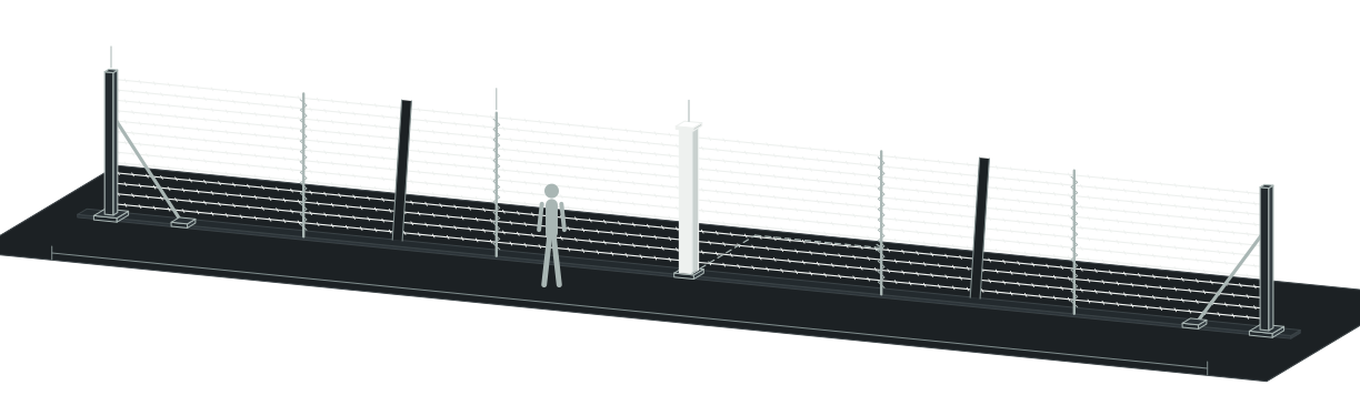
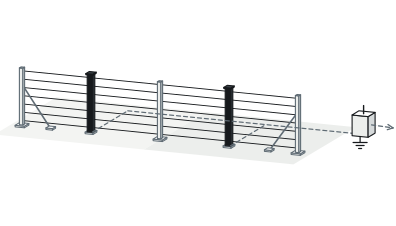
Twisted barbed sensing wires · axial force → mechanical detection010203Typical planning zone · 60 m
01End anchor post
02Spiral support post
03Central detector post · 0 W
Twisted barbed sensing wires · axial force → mechanical detection
Zero Fence Power Trenching
0 W
Purely mechanical post switches immune to HV EMI
Barrier + Sensor in One
9–20 cm
Barbed array blocks climbers across 1–2 wires per detector
Sub-Second Breach Cue
≤0.5 s
Dry-contact switching on over-threshold pull or wire cut
Nuisance Contact Filtered
On-Site Pull Threshold
Filters animal and plant contact; absorbs seasonal drift
01 — Key capabilities

Twelve Reasons Specifiers Standardize on TW-100

01

Catch Every Physical Breach

01

One Structure Blocks and Senses

Turn high-tensile twisted barbed wire directly into your perimeter alarm line.

02

Dual Pull-and-Cut Trigger

Actuate a zone alarm on over-threshold wire pull or wire cutting.

03

Distributed Multi-Detector Post

Monitor 1–2 wires per detector across 9–20 cm spacing without blind spots.

04

≤0.5 s Alarm Actuation

Close dry-contact alarm circuits in ≤0.5 s across 1,000 N/mm² strands.

02

Silence Nuisance Dispatches

05

On-Site Pull Threshold

Adjust trigger pull force on site to filter out animal and plant contact.

06

Seasonal Drift Self-Compensation

Absorb slow thermal expansion and minor soil settlement without seasonal re-tensioning.

07

Material-Based Low Upkeep

Rely on material physical properties; intact protective materials keep routine upkeep minimal.

08

0 W EMI/RFI Immunity

Eliminate post power, circuit boards, and EMI false alarms from -40°C to +72°C.

03

Drop Into Industrial Control

09

Separate Intrusion and Tamper

Isolate perimeter breach events from post housing tamper on dedicated dry contacts.

10

2,000 Vrms Isolated Zone I/O

Collect 12 DI + 6 DO channels over 2,000 Vrms optically isolated 24 VDC modules.

11

Modbus TCP + Battery Failover

Integrate via RJ-45 Modbus TCP, ≥8 relays, and automatic backup power switching.

12

Competitive Cost, Fast Dispatch

Beat peer taut-wire pricing and meet tight civil schedules with rapid factory shipping.

02 — Operating principle

How Mechanical Force Becomes a Verified Zone Alarm

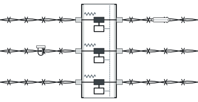
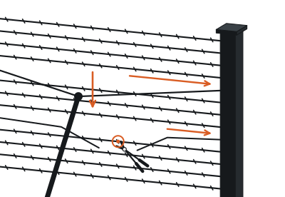
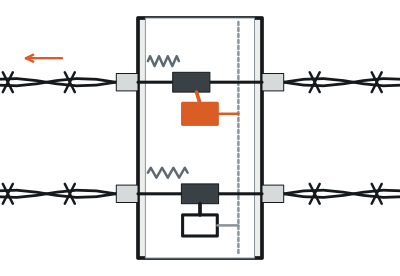
End anchor posts hold twisted stainless-steel barbed wires under static tension across each perimeter zone.

Spiral support posts lock vertical 9–20 cm wire spacing while letting axial force travel freely along each strand to the central detector post, where distributed mechanical switches monitor 1–2 wires apiece.
Breach force on span
01
Breach force on span
Climb / spread pull or wire cut
0 W post actuation
02
0 W post actuation
IP65 · 0 W · 1–2 wires / detector · intrusion and tamper dry contacts
Powered zone alarm
03
Powered zone alarm
≤0.5 s · Zone alarm · 24 VDC module → Modbus TCP controller · Powered backend

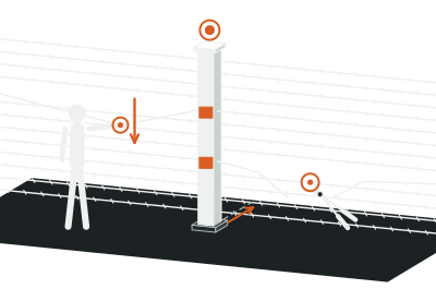
Pulling or spreading a wire past the on-site threshold—or cutting a strand to collapse resting tension—shifts the mechanical load and closes a dry-contact switch in ≤0.5 s.

Powered backend zone modules and the alarm controller read that contact state change and report the exact breached zone.

03 — Nuisance-alarm immunity

Set the Pull Threshold on Site. Let the Mechanics Absorb Seasonal Drift.

Nothing erodes guard-force trust faster than fence sensors crying wolf on windblown brush—or forcing crews to re-tension wires every winter and summer.

TW-100 eliminates both headaches mechanically inside the post.
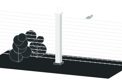
A · Animal and plant contact
On-site pull threshold · Filtered out · contact normal
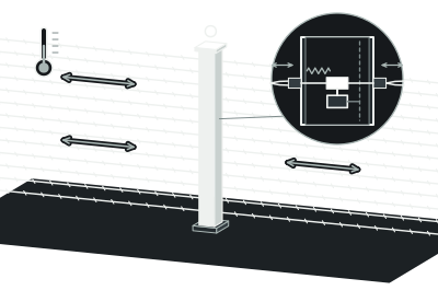
B · Slow thermal and soil shift
-40°C to +72°C · self-compensated stable baseline
C · Deliberate pull or wire cut
On-site pull threshold · Over-threshold pull / tension loss → immediate alarm · ≤0.5 s

First, an on-site adjustable pull threshold filters out animal and plant contact directly at the wire line.

Second, an internal self-compensating mechanism tracks slow thermal expansion, contraction, and minor post settlement across -40°C to +72°C—keeping resting baseline stability intact while deliberate pulls and cuts trigger in ≤0.5 s.

04 — Field deployment

Engineered for the boundary you operate.

Scenario 01 · Critical Asset Compounds

Stop Climbers at the Outer Fence—Not Inside Your Yard

Interior yard beams and video analytics only alert you after an intruder has already cleared the fence. TW-100 blocks the approach path with 1.6 mm twin-twisted 304 / 304L stainless barbed strands rated at 1,000 N/mm² tensile strength. Using a strand for footing, prying a gap, or cutting a wire cues fixed cameras to that exact perimeter zone while the physical barrier holds.

Plan this perimeter →
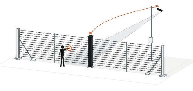
BARRIER + DETECTION AT THE OUTER LINE
Outside approach
Outside approach
TW-100 · 9–20 cm · Protected yard
Zone-matched camera cue
≤0.5 s
04 — Field deployment

Engineered for the boundary you operate.

Scenario 02 · High-Voltage and Hazardous Perimeters

Eliminate HV Switching False Alarms and Fence-Line Power Cabling

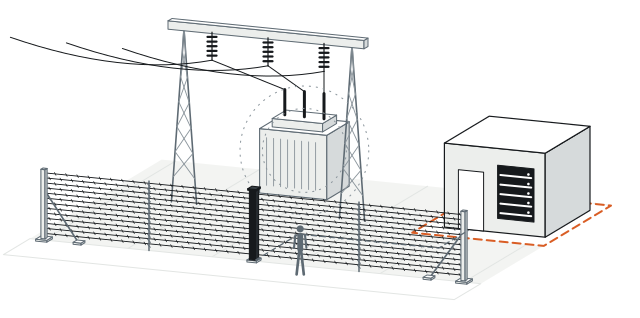
High-voltage switchyard transients and strict hazardous-area zoning turn powered fence sensors into false-alarm liabilities and permitting bottlenecks. TW-100 places 0 W at the boundary—zero circuit boards, zero power trenching, and zero RF emissions along the fence. Purely mechanical post switches ignore EMI and RFI completely while dry-contact loops terminate cleanly inside safe-area control rooms.

Plan this perimeter →
OUTDOOR PASSIVE / INDOOR POWERED
High-EMI / classified perimeter
0 W · Mechanical post · zero power / zero RF
Safe-area room
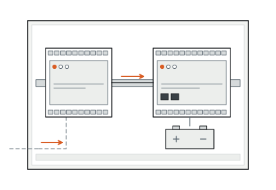
24 VDC · Dry-contact signal loop → powered collection
04 — Field deployment

Engineered for the boundary you operate.

Scenario 03 · Lifecycle Upkeep Control

Stop Sending Technicians to Remote Sites for Battery Swaps and Recalibration

Dispatching crews across unstaffed solar plants or remote utility stations to replace sensor batteries and failed outdoor boards drains multi-year maintenance budgets. TW-100 relies on the physical properties of its materials: while protective materials remain intact, the core sensing structure rarely suffers damage and needs minimal routine upkeep. IP65 post housings, structural alloy or 304 stainless steel, and bronze fittings endure harsh climates year after year.

Plan this perimeter →
MATERIAL-BASED RELIABILITY
304 / Alloy steel / Bronze · IP65 · Zero field batteries
04 — Field deployment

Engineered for the boundary you operate.

Scenario 04 · Versatile Boundary Geometry

Carry Continuous Tension Across Walls, Grade Shifts, 90° Corners, and Gates

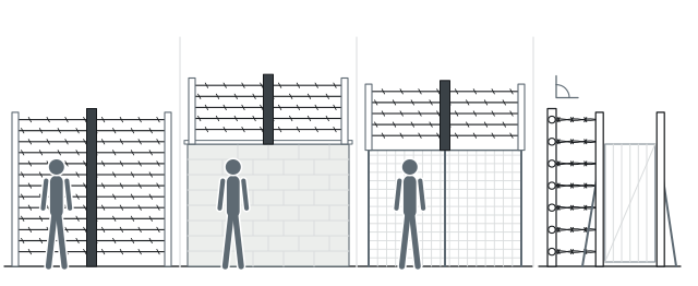
Masonry walls, sudden elevation drops, tight 90° corners, and heavy vehicle gates quickly break rigid, straight-line sensor layouts. TW-100 adapts cleanly as a freestanding barrier, an angled or vertical wall-top extension, or a structural fence-top upgrade. Engineers typically plan around 60 m zones, using corner pulley posts, wire tensioners, and gate-flank anchor posts to keep protection continuous.

Plan this perimeter →
Three standard mounting profiles
A · Freestanding barrier
B · Wall-top mounting
C · Fence-top extension
Corner pulley / gate-flank anchors
90°
04 — Field deployment

Engineered for the boundary you operate.

Scenario 05 · Control-Room Integration

Connect Directly via 2,000 Vrms Isolated I/O and Native Modbus TCP

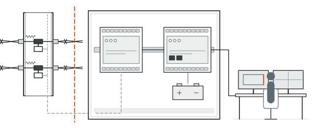
Proprietary protocol converters and unisolated field wiring slow commissioning and expose control racks to ground-loop surges. TW-100’s 24 VDC dual-zone module provides 12 DI + 6 DO channels with 2,000 Vrms optical isolation over 10/100 Mbps Ethernet. Upstream, the alarm controller delivers RJ-45 Modbus TCP, ≥8 relays (5 A at 250 VAC / 30 VDC), 8 local tamper inputs, and automatic battery failover.

Plan this perimeter →
OPEN INTERFACES. CLEAR POWER BOUNDARY.
Post intrusion + tamper
0 W · Dry contacts
Dual-zone I/O module
24 VDC · 12 DI + 6 DO · 2,000 Vrms · 10/100 Mbps
Alarm controller
RJ-45 · Modbus TCP · ≥8 DO · Backup battery
Site VMS / PSIM
Camera presets / SCADA
05 — System architecture and bill of subsystems

What Goes on the Fence at 0 W—and What Connects in the Equipment Room

TW-100 cleanly separates unpowered outdoor barrier hardware from indoor collection and control electronics—simplifying civil works, low-voltage wiring, and UPS sizing.
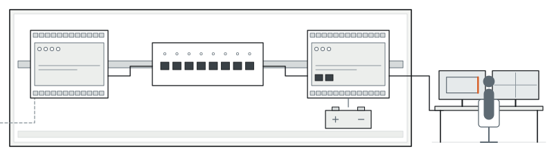
OPEN INTERFACES. CLEAR POWER BOUNDARY.
OUTDOOR PASSIVE0 W (Unpowered)Outdoor perimeter line
Zone 01 + Zone 02
01
Zone 01 + Zone 02
0 W · IP65 · Anchor posts · main / intermediate spiral posts · detector posts → signal collection
02
Dry-contact signal cable
Signal surge arrestor
INDOOR POWEREDPoweredProtected field junction cabinet or indoor equipment room
Dual-zone I/O module
03
Dual-zone I/O module
24 VDC · 12 DI / 6 DO
04
Ethernet switch / LAN
10/100 Mbps
05
Alarm controller
9–24 VDC · Modbus TCP · ≥8 DO · Backup battery
06
Security management center
VMS / PSIM

System components and trade interfaces

Subsystem Layer
Components Included
Power Status
Location and Trade Scope
01 · Tensioned Barrier Structure
End/corner anchor posts (2 per zone), main spiral posts, intermediate spiral posts, corner pulley posts, wire tensioners, U-locks, grounding stakes, and 1.6 mm twin-twisted stainless barbed wire
0 W (Unpowered)
Outdoor perimeter line · Civil and fence installation
02 · Mechanical Post Detectors
IP65 post-mounted mechanical detector array (1–2 sensing wires per detector) with separate intrusion and tamper dry-contact outputs
0 W (Unpowered)
Central/end sensor post along fence · Fence and low-voltage termination
03 · Dual-Zone Alarm I/O Module
18-channel industrial I/O unit (12 DI + 6 DO, dry/wet contact selectable, 2,000 Vrms optical isolation, 10/100 Mbps)
Powered (24 VDC nominal; 10–30 VDC, 100 mA)
Protected field junction cabinet or indoor equipment room · SI wiring
04 · Alarm Controller and Backup Power
Network alarm controller (RJ-45 10/100 Mbps, Modbus TCP, ≥8 DO relays, 8 local detector-tamper inputs, external battery monitoring and auto-failover)
Powered (9–24 VDC with adapter + external backup battery)
Control room or security equipment rack · SI commissioning
06 — Technical specifications

PerimTaut TW-100 Full Engineering Specifications

Detection Performance
Parameter
Standard Specification
Sensing Principle and Post Power
Passive mechanical tension detection; 0 W at the post, zero electromagnetic radiation
Trigger Events
On-site adjustable pull threshold (pulling/climbing/spreading) or sensing-wire cutting
Environmental Contact Filtering
Filters out animal and plant contact; mechanical self-compensation offsets slow thermal and ground shift
Alarm Response Time
≤0.5 s
Typical Planning Zone Length
60 m per zone (flexible per boundary geometry)
Barrier and Wire Mechanics
Parameter
Standard Specification
Wire Spacing and Detector Ratio
9–20 cm vertical wire spacing; 1–2 sensing wires per mechanical detector
Sensing Wire Construction
304 / 304L twisted stainless-steel barbed wire; 1.6 mm twin-wire strand, 1,000 N/mm² tensile strength (300 m/roll)
Post and Hardware Materials
Structural alloy steel or 304 stainless steel (for corrosive sites); stainless-steel U-locks and bronze fittings
Backend Zone I/O Module
Parameter
Standard Specification
Channels and I/O Capacity
18 channels total: 12 DI + 6 DO; 10/100 Mbps Ethernet communication
Input / Output Electrical Ratings
Dry contact (0: GND, 1: open) or wet contact (0: 0–3 V, 1: 10–30 VDC); output rating 30 V, 100 mA
Module Power and Isolation
24 VDC nominal supply (10–30 VDC input range, 100 mA rated current); 2,000 Vrms optical isolation
Alarm Controller
Parameter
Standard Specification
Network and Protocol
RJ-45, 10/100 Mbps auto-negotiation; native Modbus TCP protocol
Outputs and Input Impedance
≥8 digital relay outputs rated 5 A at 250 VAC / 30 VDC; 4,700 Ω input impedance
Tamper Supervision
Host enclosure tamper, host movement alarm, plus 8 local detector-tamper inputs
Controller Power and Protection
9–24 VDC input (with adapter), external backup battery voltage monitoring, automatic main/backup switching, 400 mA overcurrent protection, isolated Ethernet port
Environmental Ratings
Mechanical Post Detector
IP65 protection; -40°C to +72°C; up to 95% RH (non-condensing)
Sensing Wire and Zone I/O Module
-40°C to +70°C operating temperature
Alarm Controller
-40°C to +85°C operating temperature; 0–95% RH (non-condensing)

Above values reflect standard product technical specifications. Final post structural wind-load calculations, zone lengths, and host I/O mapping are matched to your project drawings during design.

07 — Engineering FAQ

Common Questions Before Specifying TW-100

01How are vehicle gates and pedestrian entrances protected along a TW-100 fence line?

Each TW-100 wire array terminates cleanly at dedicated anchor posts on both sides of a gate opening. Across the movable gate span itself, engineers typically pair the opening with a bistatic microwave link such as PerimWave MW-400 (5–200 m) or monitored gate contacts wired into the same alarm controller.

02When should we choose TW-100 parallel taut-wire fencing versus TW-150 monitored razor coils?

Choose TW-100 for a neat freestanding detection fence or parallel-wire wall/fence-top topping (9–20 cm wire spacing, 1–2 wires per detector). Choose PerimTaut TW-150 when your risk profile demands concertina razor-wire coils (1–3 layers on walls or freestanding corridors) with 0 W tension sensing and optional single-loop cut monitoring.

03What if our site already has kilometers of sound chain-link fencing and cannot pour new anchor footings?

Because TW-100 holds static wire tension, it requires structural anchor footings or rigid wall copings. To upgrade an existing structurally sound fence without new tensioned posts, evaluate PerimOptic FO-700 (up to 80 km fence locating), FO-750 (4 × 300 m passive optical zones), or PerimVibe VC-600 (up to 600 m locating vibration cable).

04How does TW-100 perform on total project budget and factory lead time?

TW-100 delivers competitive pricing against equivalent high-security passive taut-wire systems while saving fence-line power trenching and multi-year servicing costs. Fast factory production and dispatch keep deliveries aligned with your civil foundation and commissioning milestones.

08 — Next step

Get a Preliminary TW-100 Zone Proposal and Equipment Supply Quote

Send your perimeter layout or boundary sketch—even while civil details are still in progress. Our engineers will map anchor and detector post sections, size backend I/O and controllers, and prepare an equipment supply quotation.

01Total boundary length, corner angles, and gate openings
02Target structure: freestanding ground line, masonry wall top, or structural fence top
03Nearest indoor room or protected cabinet for 24 VDC / Modbus TCP backend hardware
04Preferred host interface (dry-contact relays, Modbus TCP, or VMS camera presets)
Substations ↗Solar and Battery Storage ↗Oil and Gas Terminals ↗Airports ↗Data Centers ↗Taut-Wire Guide ↗Power Planning Guide ↗Installation and Maintenance ↗Compare All Products ↗