Engineering Hub · Operational Requirements and Sensing Principles
How PIDS Work: Define Detection, Alarm, and Response Requirements
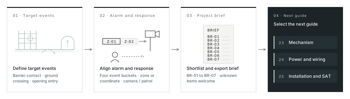
What is a perimeter intrusion detection system (PIDS), and what role does PIDS security play in overall perimeter security? A physical fence or wall delays an intruder, while a PIDS places mechanical, optical, electromagnetic, or microwave sensors along the boundary to turn climbing, cutting, or crossing into a verifiable control-room alarm. Built for facility owners, consultants, and early-stage integrators, this guide helps you settle three decisions—target events, reporting granularity, and candidate sensor families—and leave with a one-page project requirement brief.
- Decision 01 · Target Events
- Define whether alarms must fire on barrier contact, open-ground crossing, or gap entry
- Decision 02 · Alarm Granularity
- Choose discrete camera-matched zones or calibrated meter coordinates along long routes
- Decision 03 · Candidate Families
- See where PerimTaut passive taut-wire leads and where fiber, buried, or corridor sensors fit
- Takeaway Output
- Copyable 1-page requirement brief (#s06) ready for preliminary zone proposal review
01 — Event-to-response chain
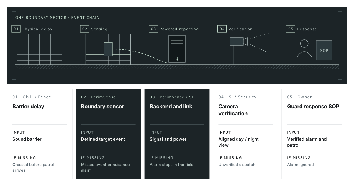
Trace Five Links Between a Physical Intrusion and Site Action
Effective PIDS connects five responsibilities along the same boundary: physical delay, intrusion detection, alarm reporting, visual verification, and patrol response. Plan the complete chain so each team and device has a clear role.
01
01 · Physical Delay (Fence / Wall / Grille)
Marks the legal boundary and slows climbing, prying, or cutting long enough for assessment and response—but reports nothing by itself.
02
02 · Boundary Sensing (Field Sensor)
Converts physical force, structural vibration, ground pressure, RF/electrostatic field change, or beam interruption into a raw contact, optical, or electronic signal.
03
03 · Processing and Transmission (Backend Module / Processor + Link)
Evaluates the signal against configured thresholds, separates tamper/fault states where supported, and transmits the zone ID or coordinate to the head-end.
04
04 · Visual Verification (Operator + Camera / Lighting)
Control-room or guard-desk staff inspect the paired camera view (supported by night illumination or thermal imaging) to confirm what triggered the event.
05
05 · Security Response (Patrol / Site SOP)
Authorized personnel intercept, secure the sector, and log the event outcome under written site procedures.
02 — Define detection tasks first
Classify What Must Trigger an Alarm Across Four Boundary Tasks
Before comparing 13 model codes, group each section of your perimeter by where an intruder interacts with the boundary—and remember that vehicle gates, culverts, and corners almost always need dedicated handling.
| Detection Task Category | Target Intrusion Action | Typical Boundary Condition | Candidate Sensing Direction | Verification Condition to Check |
|---|---|---|---|---|
| Task 01 · Barrier contact with physical delay | Climbing pull, wire spreading, wire cutting, or concertina-coil cutting | New security line, high-target inner compound, or structural wall/fence-top upgrade | Passive mechanical taut-wire (TW-100, TW-150) or modular concealed-fiber fence (FF-200) | Footing/wall load capacity; rigid coil force transfer on TW-150; architectural profile on FF-200 |
| Task 02 · Existing-fence climb or fabric cut | Cutting mesh, climbing fabric, lifting bottom wire, or scaling a stepped wall | Structurally sound existing chain-link, weldmesh, palisade, or masonry wall kept in place | Attached passive fiber (FO-750, FO-700), locating cable (VC-600), wall field (EF-350), or sensor light (LP-500) | Repair loose mesh/gates first; decide fixed zone vs meter coordinate; check fence-line power if adding LP-500 |
| Task 03 · Concealed ground or waterway crossing | Walking, running, or crawling across an interior setback lawn, choke-point path, or stream | Visually open grounds, sterile buffer strip between double fences, or shallow waterway | Buried RF coaxial corridor (BF-300) or dry-land sub-surface pressure units (PM-280) | Soil drainage, paving build-up, no-dig root/utility zones; review water depth/flow specifically for BF-300 |
| Task 04 · Gate corridor, culvert, or work gap | Crossing a closed vehicle lane, temporary construction opening, or below-grade storm drain | Breaks where continuous fence wires or fibers must stop | Fixed gate microwave (MW-400), portable battery link (MW-450M), or culvert fiber grille (FF-250) | Flat unobstructed sightline and gate arming schedule (MW); culvert storm flow and debris access (FF-250) |
03 — Alarm quality definitions
Keep Detection, Nuisance Triggers, System Faults, and Unverified Alarms Separate
Asking for "99% accuracy" in a tender specification leaves everyone guessing what is being measured. Operational clarity requires tracking four distinct event buckets—alongside whether operators could verify the event visually:
| Event Bucket | Operational Definition | What Drives It on Site | How Consultants and Owners Specify It |
|---|---|---|---|
| 01 · Target Intrusion Detection | System raises the expected zone or coordinate alarm when a defined climb, pull, cut, or crossing action occurs | Sensor physical coupling, proper installation tension/alignment, and calibrated threshold | Define exact simulated intrusion actions, test locations per zone, and witnessed SAT pass rules (25-install-guide.html) |
| 02 · Environmental / Operational Nuisance Triggers | Real physical disturbance from non-threat sources triggers an alarm (wind, rain, animal and plant contact, adjacent traffic, or unscheduled staff) | Loose host fencing, overhanging branches, unscheduled gate traffic, or unadjusted thresholds | Specify electromagnetic and radio-frequency interference (EMI/RFI) immunity where needed, on-site adjustable pull thresholds or processor sensitivity tuning, fence preparation, and gate arming schedules |
| 03 · Equipment, Power, Wiring, and Tamper Faults | Loss of supply, opened enclosure tamper, severed optical fiber, or supervised cable open/short | AC outage exceeding UPS, conduit damage, connector corrosion, or cabinet tampering | Require separate fault/tamper reporting channels (24-power-guide.html) so hardware faults never masquerade as intrusions |
| 04 · Unclassified / Unverified Events | An alarm fires, but operators cannot determine the cause because camera views are blind, dark, or delayed | Missing camera preset alignment, unlit rural fence lines, or slow patrol dispatch | Pair every zone or coordinate segment with a day/night camera view (adding lighting such as LP-500 where needed) |
04 — Reporting granularity
Compare Discrete Zone Alarms and Continuous Meter Coordinates on the Same Fence
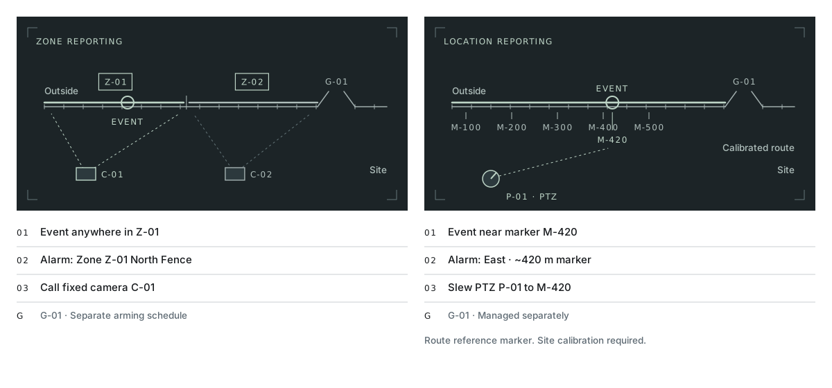
Every PIDS reports either which named physical zone entered alarm or a distance coordinate along a continuous sensor cable. Choose granularity from your perimeter length and camera layout—keeping two operational realities in mind:
01
When Discrete Zone Reporting Fits Best (TW-100, TW-150, FF-200, FO-750, FF-250, PM-280, EF-350, MW-400)
Each zone (for example, a 50–300 m fence sector, a culvert grille, or a gate lane) maps 1-to-1 to a fixed camera view and a landmark name such as North Transformer Line. Highlight the named zone on the head-end map to guide camera verification and patrol response.
02
When Meter-Level Coordinate Reporting Fits Best (FO-700, VC-600, BF-300)
On multi-kilometer fences or wide buried corridors where fixed cameras cannot cover every meter economically, continuous locating (FO-700 nominal ±4 m up to 80/100 km; VC-600 within 3 m up to 600 m; BF-300 nominal ±1 m up to 800 m) slews PTZ cameras and directs patrols to numbered fence markers.
03
Gate State Exception
In both reporting modes, active vehicle gates require scheduled armed/disarmed operating states so authorized daytime deliveries do not flood the operator screen.
05 — Candidate shortlist and flagship role
Match Primary Site Conditions—Seeing Clearly Where PerimTaut Fits and Where Alternatives Lead
Once target events and reporting granularity are clear, narrow your shortlist by the dominant physical condition on each boundary segment:
| Dominant Boundary Condition | Candidate Direction to Evaluate First | Core Engineering Rationale | Next Deep-Dive Page |
|---|---|---|---|
| 01 · Boundary must physically delay climbing/cutting AND report pull/cut with minimal upkeep | PerimTaut Mechanical Taut-Wire (TW-100 / TW-150) | 0 W mechanical post switches operate unaffected by EMI/RFI; on-site adjustable pull thresholds filter out animal and plant contact; material-based core sensing structure rarely suffers damage while its protective materials remain intact; competitive same-tier pricing and fast dispatch | Guide 23 · Taut-Wire Mechanisms and Spec Worksheet |
| 02 · Sound existing fence kept intact, or new architectural commercial frontage | Passive Optical Fiber (FO-750, FO-700, FF-200) or Locating Cable (VC-600) | Avoids heavy new tension-anchor footings on miles of existing mesh (FO-750 zoned, FO-700/VC-600 locating) or hides 0 W fiber inside clean modular fence rails (FF-200) | Products · Fence Detection Comparison |
| 03 · Visually open lawns, sterile inner strips, or shallow estate waterways | Concealed Ground Sensors (BF-300 / PM-280) | Keeps hardware invisible below grade: BF-300 covers continuous buried RF corridors (and project-reviewed water crossings); PM-280 covers dry-land choke-point paths | Products · Concealed Ground Sensors |
| 04 · Vehicle gates, culverts, dark rural fences, or temporary construction gaps | Opening and Auxiliary Sensors (MW-400, MW-450M, FF-250, LP-500) | Closes non-fence gaps across clear gates (MW-400), temporary work openings (MW-450M), submerged drains (FF-250), or unlit fence camera views (LP-500) | <strong><a href="16-applications.html">Applications · Find Your Site Type</a></strong> |
| 05 · Uncertain where field power stops or how UPS/cables should be budgeted | System Power and Wiring Architecture Review | Maps A1/A2/B/C topologies, L1–L2 cable limits, P = V × I active loads, and F1–F6 outage survival across any combination above | Guide 24 · Passive Sensing and System Power |
06 — Copyable project requirement brief
Build Your One-Page Project Requirement Brief
Copy or print this seven-row worksheet to align internal stakeholders before requesting a preliminary zone proposal and equipment supply quote. You do not need to upload confidential full-site CAD drawings on first contact—rough sketches work, and open items can simply be marked Unknown.
| Brief Field ID | What to Record for Your Project | Who Typically Provides / Confirms | Your Project Entry (Unknown Allowed) |
|---|---|---|---|
| BR-01 · Protected assets and boundary segments | Facility type, assets protected, segment names/numbers, approximate lengths, gates, culverts, and transitions (a simple sketch is sufficient—no sensitive blueprints needed upfront) | Facility Owner / Consultant | [Fill segments and lengths / Unknown] |
| BR-02 · Target intrusion events to detect | Specific actions that must raise an alarm (climbing, wire spreading/cutting, mesh cutting, open-ground crossing, or culvert entry) and active hours per zone | Owner Security / Consultant | [Fill target actions and hours / Unknown] |
| BR-03 · Existing structure and environment | Current fence, wall, or coil state; wind, vegetation, and local wildlife activity; temperature extremes or coastal/chemical corrosion; adjacent road/rail traffic or HV plant | Site Operations / Fence Contractor | [Fill structure and exposure / Unknown] |
| BR-04 · Required alarm and fault information | Discrete zone ID vs continuous meter location; where alarms display; paired camera/lighting verification workflow; whether power/line faults require separate outputs | System Integrator / Owner Security | [Fill zone vs location and VMS / Unknown] |
| BR-05 · Power, conduits, and head-end | Available indoor/cabinet power points, existing ducts/cables, installed alarm panel or VMS brand/interface, and target UPS backup runtime (write Unknown if not yet surveyed) | System Integrator / EPC Electrical | [Fill power points or Unknown] |
| BR-06 · Response team and maintenance reality | Who verifies alarms, who dispatches to the boundary (and travel/permit time), who handles vegetation/hardware checks, and whether current nuisance logs exist | Owner Operations / Facilities | [Fill response and upkeep notes / Unknown] |
| BR-07 · Project stage and separate target dates | New build vs retrofit; planning, tender, or construction stage; list separate target dates for (a) factory dispatch, (b) site delivery, and (c) commissioning/handover | Project Manager | [Fill stage and target dates / Unknown] |
07 — Deep-dive guides and project review
Take Your Next Engineering Step—or Send Your One-Page Brief
Guide 23
Taut-Wire Detection: Compare Mechanisms and Specify the System
Who Needs It
Consultants and SI leads evaluating physical-delay barriers.
What You Take Away
TW-100 vs TW-150 force-transfer diagrams, threshold vs slow-drift separation, fair strain-gauge/fiber signal chains, and the copyable SP-01–SP-06 specification worksheet.
Action
Open Guide 23: Taut-Wire Comparison →
Guide 24
Passive Sensing, System Power, and Wiring Architecture
Who Needs It
Electrical designers, EPC engineers, and system integrators.
What You Take Away
Where 0 W stops, A1/A2/B/C wiring topologies, L1–L2 cable schedule, P = V × I node load and UPS worksheet, and the F1–F6 failure recovery matrix.
Action
Open Guide 24: Power and Wiring →
Guide 25
PIDS Installation, Commissioning, and Maintenance Checklist
Who Needs It
Project managers, installers, commissioning engineers, and facility owners.
What You Take Away
Numbered pre-work survey log, four-stage delivery table, pre-commissioning ITP, TW threshold re-verification sheet, SAT handover checklist, and 3-layer upkeep plan.
Action
Open Guide 25: Installation and SAT Checklist →
- Prompt: Ready to discuss your perimeter? Paste your 1-page requirement brief—even with Unknown items—to receive a preliminary zone proposal and PerimSense equipment supply quote, or request product information on candidate models.
- Secondary Directory Links: Browse by facility type on Applications · Compare all 13 models on Products Overview →