Home/Products/PerimTaut TW-150
PerimTaut TW-150 · Passive Tension-Sensing Razor Wire Coils

Razor Wire That Resists Entry—and Reports Every Cut or Pull.

Unmonitored razor coils only delay intruders while bolt cutters work through the barrier unseen. PerimTaut TW-150 turns 1–3 wall-top or freestanding coil layers into a 0 W mechanical detection line with adjustable pull thresholds, optional 1-loop cut sensing, and 3 zone alarm contacts.
Share your boundary layout for a preliminary zone proposal and equipment supply quote.
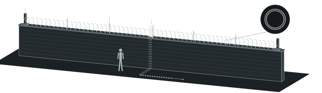
Concertina Razor Coil · 1–3 Wall Layers01020306
01End anchor post
02Spiral support post
03Detector post · 0 W mechanical switch
06Optional built-in anti-cut wire (1-loop cut)
Concertina razor coil · 1–3 wall layers
Zero Fence Power Trenching
0 W
Mechanical post detectors completely immune to HV EMI and RFI
Loop-Level Cut Verification
1 Loop
Optional internal anti-cut wire reports any severed coil loop
Scalable Barrier Deterrence
1–3 Layers
Wall-top arrays, steep-slope lines, or 60 cm freestanding coils
Classified Dispatch Signals
3 Contacts
Separate zone intrusion, tamper, and cut dry-contact outputs
01 — Key capabilities

Twelve Reasons High-Security Sites Specify TW-150

01

Turn Passive Coils into Active Detection

01

Active Deterrent Coils

Unite concertina razor physical deterrence with immediate pull and cut intrusion alarms.

02

1-Wire Direct Sensing

Connect 1 tensioned sensing wire per mechanical detector for positive force transfer.

03

1-Loop Anti-Cut Option

Specify internal anti-cut wire coils to report severing of any 1 loop.

04

3 Classified Contacts

Deliver separate zone intrusion, tamper, and cut dry contacts for targeted response.

02

Silence Nuisance Alarms and Field Servicing

05

Adjustable Pull Threshold

Tune trigger force on site to filter out animal and plant contact.

06

Self-Compensating Mechanics

Absorb slow thermal drift and soil settlement automatically without seasonal wire re-tensioning.

07

Material-Based Low Upkeep

Protect core mechanics through material physics, minimizing routine servicing across remote perimeters.

08

0 W EMI-Immune Posts

Eliminate outdoor sensor power cabling and block high-voltage substation EMI alarms.

03

Fit Tough Perimeters and Industrial Control Rooms

09

1–3 Wall-Top Layers

Stack 1–3 monitored razor-coil layers atop existing masonry or concrete perimeter walls.

10

60 cm Freestanding Arrays

Build 2 m vertical barriers with 3 × 60 cm coils and 1 m overhangs.

11

Corrosion-Resistant Steel

Select stainless-steel hardware to resist coastal salt spray and harsh chemical atmospheres.

12

Modbus TCP Integration

Connect 2,000 Vrms isolated zone modules and Modbus TCP controllers to site VMS.

02 — Operating principle

How Coil Force and Loop Cuts Become Zone Alarms

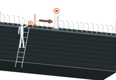
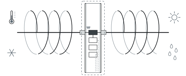
Anchor posts tension a stainless sensing wire directly through the concertina razor-wire coil, securing the barrier while transferring axial load shifts to the detector post.

Each 0 W mechanical detector monitors 1 sensing wire: pulling the coil beyond the on-site adjustable pull threshold—or cutting the monitored coil or sensing wire—shifts mechanical balance and trips a zone alarm, while internal self-compensation absorbs slow temperature and soil drift.
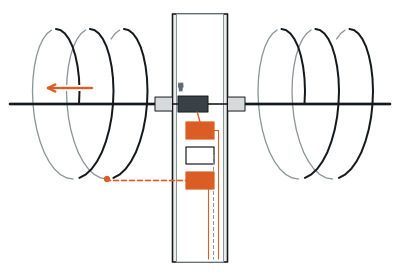
Attack on Razor Coil
01
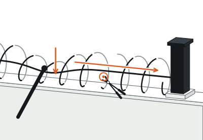
Attack on razor coil
1 wire / detector · 0 W → 3 contacts
0 W Post Switching
02
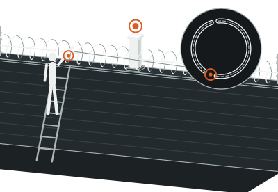
0 W post switching
Optional internal anti-cut wire · 1 open loop → cut contact
Powered Zone Reporting
03
Powered zone reporting
Protected equipment room · Alarm / camera coordination

Adding the optional built-in anti-cut wire extends detection to every loop, firing a dedicated cut contact whenever any 1 coil loop is severed.

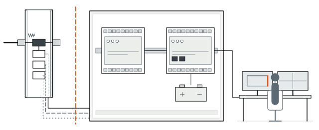
Powered backend modules read all 3 switch states and report the breached zone.

03 — Single-loop cut and nuisance defense

Catch Bolt Cutters on Any Single Loop—Without Wildlife False Alarms.

Security directors worry that an intruder with insulated bolt cutters could snip 1 outer loop of razor wire to slip through without pulling the main support strand hard enough to trip a basic tension sensor—or that lowering sensitivity threshold settings will invite constant wind and wildlife false alarms.

TW-150 closes that gap with 2 independent passive mechanisms at 0 W.
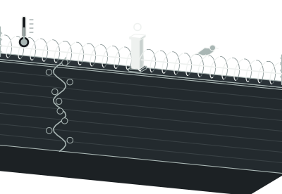
Wildlife, Plants, and Thermal Drift
State A
Wildlife, plants, and thermal drift
Below pull threshold + self-compensated (-40°C to +72°C)
Filtered out · Normal standby
Coil Pull or Main Sensing-Wire Cut
State B
Coil pull or main sensing-wire cut
Axial tension surge or loss on 1 sensing wire
Zone intrusion contact actuated
Single Razor-Loop Snip
State C
Single razor-loop snip
Any 1 individual loop severed (optional anti-cut wire)
Dedicated cut contact actuated

Along the support axis, an on-site adjustable pull threshold filters out animal and plant contact while mechanical self-compensation absorbs slow thermal drift from -40°C to +72°C, keeping pull and main-wire cut alarms crisp.

Inside the spiral itself, specifying coils with the built-in anti-cut wire monitors every turn directly: severing any 1 individual loop breaks the circuit and fires a dedicated cut alarm.

04 — Field deployment

Engineered for the boundary you operate.

Scenario 01 · Wall-Top Coil Renewal

Turn Scheduled Razor-Wire Replacement into an Active Alarm Upgrade

Rusted razor coils atop masonry walls give facilities a false sense of security because night cutters can breach decayed steel without triggering a single control-room alert. During routine perimeter refurbishment, TW-150 replaces passive topping with 1–3 layers of tension-monitored razor coils anchored directly to existing wall copings. Facility owners preserve their civil wall structure while turning silent steel into an active 0 W detection boundary.

Plan this perimeter →
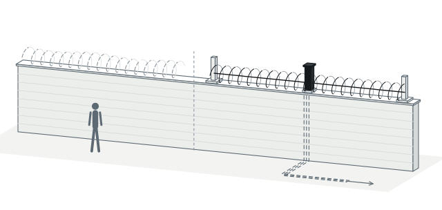
Wall-top upgrade comparison
Before upgrade
01
Before upgrade
Unmonitored coils
02
Monitored concertina
1 wire / detector · 0 W → 3 contacts
04 — Field deployment

Engineered for the boundary you operate.

Scenario 02 · High-Consequence Compounds

Deploy Multi-Layer Freestanding Coils Where Breach Consequences Are Severe

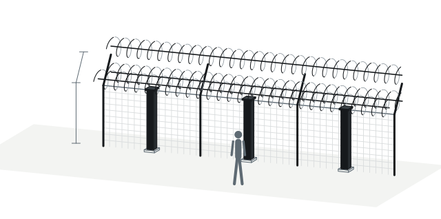
Prisons, nuclear plants, military depots, and high-speed rail corridors face determined breach attempts where light fencing yields in seconds. TW-150 builds a heavy freestanding profile combining a 2 m vertical barrier section, 3 layers of 60 cm diameter concertina razor coils, and a 1 m outward-inclined overhang. Every monitored coil line connects 1 sensing wire per detector so physical entanglement and alarm dispatch happen simultaneously.

Plan this perimeter →
Typical heavy freestanding TW-150 geometry
2 m Vertical Barrier Section2 m1 m3 × 60 cm
2 m vertical barrier section
3 × 60 cm concertina coil layers
1 m outward-inclined support
1 sensing wire per detector
04 — Field deployment

Engineered for the boundary you operate.

Scenario 03 · Steep Cliffs and Slopes

Carry Continuous Monitored Protection Across Cliffs and Abrupt Gullies

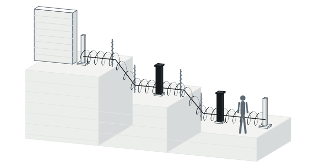
Rigid panel fences and straight-line optical beams break down on rocky cliffs, steep embankments, and sudden grade drops—leaving dead zones where intruders bypass the main gate. TW-150 bridges rugged terrain with a contoured 1-layer razor-coil layout tensioned between stepped anchor and support posts. Self-compensating mechanics track slow slope creep automatically, keeping difficult terrain transitions continuously armed.

Plan this perimeter →
Stepped steep-terrain deployment
Main Perimeter Wall / Fence
Main perimeter wall / fence
Steep cliff / embankment
1-layer contoured TW-150 line
Stepped anchor terminations
04 — Field deployment

Engineered for the boundary you operate.

Scenario 04 · Harsh and Remote Perimeters

Survive Salt Spray, Desert Heat, and Deep Freeze Without Field Power

Remote border lines, coastal petrochemical yards, and desert infrastructure punish powered field sensors with lightning surges, salt corrosion, and costly battery-replacement trips. TW-150 runs at 0 W from -40°C to +72°C (up to 95% RH) with a stainless-steel option for corrosive sites, and its sensing core relies on the physical properties of its materials—so while protective materials remain intact, core damage is rare and routine upkeep stays minimal.

Plan this perimeter →
Harsh-environment durability chain
-40°C to +72°C
-40°C to +72°C
Up to 95% RH
Stainless-steel option for corrosive sites
Intact protective materials → rare core damage
Minimal routine upkeep
0 W field line
04 — Field deployment

Engineered for the boundary you operate.

Scenario 05 · Classified Control-Room Integration

Distinguish Intrusion, Tamper, and Coil Cuts Straight Inside Your VMS

Single-contact fence alarms force control-room operators to treat enclosure tampering and active bolt-cutter breaches identically during high-stress night shifts. TW-150 provides 3 separate switch outputs per zone—intrusion, tamper, and cut—wired into 24 VDC dual-zone I/O modules with 12 DI + 6 DO channels and 2,000 Vrms optical isolation. Network controllers deliver native RJ-45 Modbus TCP, ≥8 relay outputs, and automatic backup-battery failover.

Plan this perimeter →
Classified alarm signaling
3 Zone Contacts
3 zone contacts
Intrusion / tamper / cut
Dual-zone module
24 VDC · 12 DI + 6 DO · 2,000 Vrms
Alarm controller
Modbus TCP · ≥8 DO · Battery failover
VMS / PSIM camera cue
05 — System architecture and bill of subsystems

What Sits on the Perimeter at 0 W—and What Connects Indoors

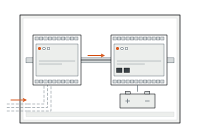
PerimTaut TW-150 keeps all outdoor razor-coil barriers and post switches completely passive at 0 W while concentrating powered I/O collection and Modbus TCP controllers inside protected cabinets or control rooms.
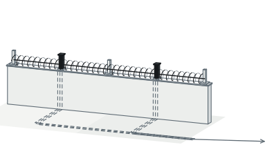
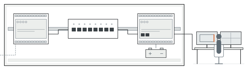
PASSIVE FIELD0 W (Unpowered)Outdoor perimeter boundary
Outdoor Razor-Coil Zone
01
Outdoor razor-coil zone
0 W unpowered
02
Anchor post · Spiral post · Detector post
1 wire / detector
POWERED BACKENDPoweredProtected junction cabinet or equipment room
3 Dry-Contact Pairs
03
3 dry-contact pairs
Intrusion / tamper / cut
04
Dual-zone I/O module
24 VDC · 12 DI + 6 DO
05
Ethernet LAN
10/100 Mbps
06
Alarm controller + battery
9–24 VDC · Modbus TCP · ≥8 DO
07
Control room VMS / PSIM
Alarm dispatch + camera cue

System components and trade interfaces

Subsystem Layer
Components Included
Power Status
Location and Trade Scope
01 · Monitored Razor-Coil Barrier
Concertina razor-wire coils (1–3 wall layers, 1-layer slope, or 3 × 60 cm freestanding with 2 m vertical and 1 m overhang), optional built-in anti-cut wire, anchor posts, spiral support posts, and tensioned sensing wires
0 W (Unpowered)
Outdoor perimeter boundary · Civil and barrier installation
02 · Mechanical Post Detectors
Post-mounted mechanical tension detectors (1 sensing wire per detector) with 3 dry-contact outputs per zone (intrusion, tamper, and cut)
0 W (Unpowered)
Detector post along barrier · Barrier and low-voltage termination
03 · Dual-Zone Alarm I/O Module
18-channel industrial I/O module (12 DI + 6 DO, 2,000 Vrms optical isolation, 10/100 Mbps Ethernet)
Powered (24 VDC nominal; 10–30 VDC, 100 mA)
Protected junction cabinet or equipment room · SI wiring
04 · Alarm Controller and Backup Power
Network alarm controller (RJ-45 10/100 Mbps, Modbus TCP, ≥8 DO relays, 8 local detector-tamper inputs, external battery monitoring and auto-failover)
Powered (9–24 VDC with adapter + external backup battery)
Security control room or equipment rack · SI commissioning
06 — Technical specifications

PerimTaut TW-150 Full Engineering Specifications

Detection Performance
Parameter
Standard Specification
Sensing Principle and Post Power
Passive mechanical tension sensing; 0 W at the post, immune to EMI and RFI, zero RF emissions
Sensing Wires per Detector
1 tensioned sensing wire per mechanical detector
Pull and Cut Triggering
On-site adjustable pull threshold; alarms on coil pulling, coil cutting, or sensing-wire cutting
Individual Loop Cut Monitoring
Optional built-in internal anti-cut wire triggers a cut alarm when any 1 coil loop is severed
Environmental Drift and Contact Filtering
Filters out animal and plant contact; self-compensating mechanics offset slow soil movement and temperature changes
Per-Zone Switch Outputs
3 dry-contact switch outputs per zone: zone intrusion, tamper protection, and cut detection
Alarm Controller
Parameter
Standard Specification
Network and Relay Capacity
RJ-45 10/100 Mbps auto-negotiation; native Modbus TCP; ≥8 relay outputs rated 5 A at 250 VAC / 30 VDC; 4,700 Ω input impedance
Supervision and Backup Power
9–24 VDC input (with adapter), external battery monitoring and auto-failover, 400 mA overcurrent protection, enclosure tamper/movement + 8 detector-tamper inputs
Barrier Configurations
Parameter
Standard Specification
Wall-Top and Slope Layouts
1–3 razor-coil layers on existing perimeter walls; 1-layer layout for cliffs and steep terrain; flexible zone length
Typical Freestanding Geometry
2 m vertical barrier section + 3 layers of 60 cm diameter concertina razor coils + 1 m outward-inclined support
Materials and Durability
Material-based low-upkeep core (rarely damaged while protective materials remain intact); optional stainless steel for corrosive sites
Backend Zone I/O Module
Parameter
Standard Specification
Channels and Isolation
18 channels (12 DI + 6 DO); dry/wet contact selectable; 2,000 Vrms optical isolation; 10/100 Mbps Ethernet
Module Power Input
24 VDC nominal (10–30 VDC range, 100 mA rated current); output contact rating 30 V, 100 mA
Environmental Ratings
Mechanical Post Detector
-40°C to +72°C operating temperature; 0–95% RH (non-condensing); unaffected by wind, rain, hail, snow, ice, dust, and UV
Backend Module and Controller
Dual-zone I/O module: -40°C to +70°C; Alarm controller: -40°C to +85°C, 0–95% RH (non-condensing)

Above values reflect standard product technical specifications. Coil layer count, post footing loads, zone lengths, and I/O mapping are matched to your project drawings during detailed design.

07 — Engineering FAQ

Questions Specifiers Ask Before Ordering TW-150

01When should we specify TW-150 tension razor coils instead of TW-100 parallel taut-wire fencing?

Specify PerimTaut TW-150 when your perimeter demands aggressive visual deterrence and concertina entanglement—such as 1–3 wall-top coil layers, 1-layer cliff lines, or 3 × 60 cm freestanding barriers with optional 1-loop cut sensing. Choose PerimTaut TW-100 when you prefer a clean, flat vertical array of parallel barbed wires at 9–20 cm spacing.

02Can we clip TW-150 mechanical detectors directly onto old, rusted razor wire already sitting on our wall?

To guarantee uniform axial tension transfer and reliable 0 W switching, TW-150 is supplied as an engineered barrier-and-sensor assembly pairing fresh concertina coils, tensioned sensing wires, anchor posts, and support posts—making scheduled wall-top coil replacement the ideal window to upgrade.

03When do we need the optional built-in anti-cut wire versus standard tension sensing?

Standard TW-150 already triggers an alarm whenever someone pulls the coil or cuts the monitored structure or its 1 tensioned sensing wire. Add the optional built-in internal anti-cut wire on high-consequence zones where you want immediate cut reporting if an attacker quietly snips even 1 individual outer loop without pulling the coil.

04How do vehicle gates and drainage culverts stay protected along a TW-150 perimeter?

TW-150 coil spans terminate at rigid anchor posts flanking each opening. Pair movable vehicle gates with PerimWave MW-400 microwave links (5–200 m) and seal underwater culverts or storm drains with PerimGrille FF-250 submersible optical grilles, feeding all alarms into the same control room.

08 — Next step

Request a Preliminary TW-150 Zone Plan and Equipment Supply Quote

Share your boundary drawings or wall profile for a tailored TW-150 engineering takeoff. We will map coil layer configurations, anchor and detector post positions, optional anti-cut coil sections, and backend I/O sizing.

01Total perimeter length, corner angles, steep-slope sections, and gate openings
02Target profile: 1–3 wall-top coil layers, 1-layer cliff run, or freestanding multi-layer barrier
03Zones requiring optional built-in anti-cut wire (1-loop cut) or stainless-steel corrosion hardware
04Nearest indoor room or cabinet location for 24 VDC I/O modules and Modbus TCP controllers
Substations and Nuclear ↗Oil and Gas Terminals ↗Rail and Airports ↗Solar and Storage ↗Taut-Wire Guide ↗Power Planning Guide ↗Installation and Maintenance ↗Compare All Products ↗