Home/Products/PerimOptic FO-750
PerimOptic FO-750 · Zoned Fiber-Optic Fence Intrusion Detection

Protect 4 Fence Zones at 0 W. Keep the 2 W Processor up to 20 km Away.

Detect cutting, climbing, and structural fence damage across 4 independent perimeter zones of up to 300 m each. PerimOptic FO-750 links 0 W EMI-immune boundary fiber through up to 20 km of non-sensing lead-in cable to a 2 W PoE processor with local alarm buffering.
Share your boundary layout for a preliminary zone proposal and equipment supply quote.
0 W field · zone alarm010203040506
01Zones 01–04 · Up to 300 m each (0 W)
02Passive start / end zone elements
03Non-sensing lead-in fiber · Up to 20 km
04SC/APC · 1,550 nm optical link
05Equipment room · 2 W processor (PoE / 12–48 VDC)
066 Form C relays + Ethernet + local buffer
0 W field · zone alarm
Four-Sided Station Zoning
4 × 300 m
Independent fence alarm zones managed by one compact processor
Remote Control-Room Placement
20 km
Non-sensing lead-in fiber keeps active electronics off the perimeter
Zero Fence Power Trenching
0 W
Dielectric optical fence cable immune to EMI and lightning
Single-Cable PoE Power
2 W
Ultra-low processor draw over PoE or 12–48 VDC supply
01 — Key capabilities

Twelve Engineering Reasons Critical Compounds Choose FO-750

01

Catch Fence Breaches by Sector

01

4 × 300 m Fence Zones

Monitor 4 separate perimeter sections up to 300 m each from one unit.

02

Cut and Climb Detection

Capture fabric cutting, climbing, and structural fence damage before intruders clear the barrier.

03

1,550 nm Optical Interferometry

Convert subtle mechanical fence vibrations into high-contrast 1,550 nm laser phase shifts.

04

Adaptive Weather Filtering

Suppress uniform wind and rain vibration automatically to cut nuisance patrol dispatches.

02

Keep Power and Electronics Indoors

05

20 km Non-Sensing Lead-In

Route up to 20 km of passive lead-in fiber back to existing control rooms.

06

0 W Boundary Hardware

Eliminate field power trenching, outdoor cabinets, and conductive electronics at 0 W.

07

EMI and Lightning Immunity

Block high-voltage substation EMI and lightning surges across dielectric glass sensing fiber.

08

2 W PoE or DC Operation

Power the 2 W processor via single-cable PoE or 12–48 VDC station supply.

03

Protect Continuity and Integration

09

Local Outage Alarm Buffer

Buffer intrusion alarm records inside the processor whenever IP network links drop.

10

6 Form C Relays + 2 Inputs

Trigger NVR presets and panels directly via 6 configurable relays and 2 inputs.

11

444 g Multi-Mount Chassis

Fit the 444 g unit onto DIN rails, equipment racks, or outdoor enclosures.

12

-40°C to +70°C Surge Defense

Withstand -40°C to +70°C extremes with integrated surge protection across all terminals.

02 — Operating principle

How Fence Vibration Shifts 1,550 nm Laser Interference into a Zone Alarm

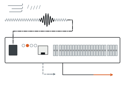
Through an SC/APC optical interface, the FO-750 processor sends 1,550 nm laser light across up to 20 km of non-sensing lead-in cable into 4 fence-mounted sensing zones of up to 300 m each.

Passive start and end elements define each monitored fence section along a 12-core single-tube loose-tube 9/125 μm single-mode cable (0.24 dB/km attenuation), which carries both optical sensing and alarm signal transmission at 0 W.
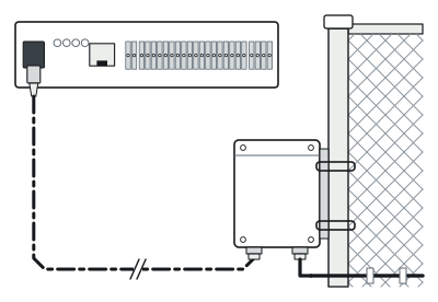
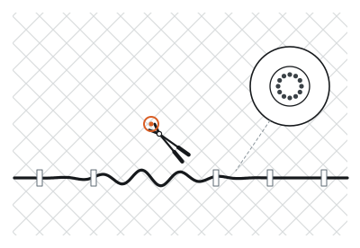
Passive Optical Feed
01
Passive optical feed
Up to 20 km lead-in → 4 × 300 m zones (start / end nodes)
Interferometric Phase Shift
02
Interferometric phase shift
Climb or cut vibration on 9/125 μm fiber (1,550 nm)
Verified Zone Alarm
03
Verified zone alarm
Wind and rain filtered → PoE Ethernet + 6 Form C relays

Cutting, climbing, or prying the fence vibrates the fiber and alters its laser interference pattern; adaptive processing filters out wind and rain noise before outputting the breached zone over PoE Ethernet or 6 Form C relays.

03 — Remote power and network continuity

Zero Power Along the Fence. Zero Lost Events During Network Outages.

Trenching outdoor power cables around remote unmanned stations—or losing intrusion records whenever a rural WAN link drops—creates costly civil overruns and dangerous security blind spots.
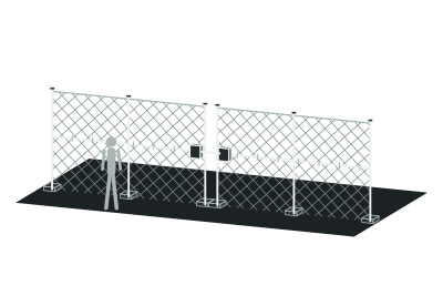
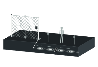
Remote Perimeter
01
Remote perimeter
0 W passive fiber
Up to 20 km Non-Sensing Lead-In
02
Up to 20 km non-sensing lead-in
Normal IP Link
State A
Normal IP link
Live Ethernet reporting (PoE, 2 W)
Network Outage
State B
Network outage
Local processor alarm buffer + 6 Form C relays (1 A, 30 VDC)

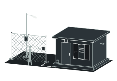
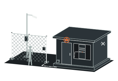
FO-750 leaves 0 W passive optical cable on the perimeter and pulls the 2 W processor up to 20 km back to an indoor rack powered by PoE or 12–48 VDC.

When upstream IP connectivity is interrupted, onboard local alarm buffering stores intrusion events inside the processor while 6 Form C relays (1 A, 30 VDC) continue driving local sirens and NVR triggers—preserving your complete event record until the network recovers.

04 — Field deployment

Engineered for the boundary you operate.

Scenario 01 · Four-Sided Utility and Energy Yards

Give Every Wall of Your Compound Its Own Dedicated Alarm Sector

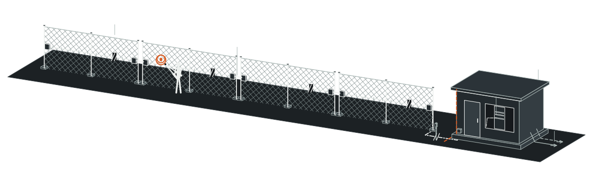
Wrapping an entire substation or battery yard into a single unsegmented alarm loop forces guards to inspect all four walls in darkness to find where an intruder cut through. FO-750 provides 4 independent detection zones of up to 300 m each (up to 1,200 m combined fence coverage per processor), mapping naturally to North, East, South, and West fence runs. Passive start and end elements isolate each side cleanly so fixed cameras and patrols respond straight to the breached boundary.

Plan this perimeter →
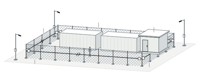
Four-sided compound layout
Zone 01 · North Fence0102030405
01
Zone 01 · North fence
Up to 300 m
02
Zone 02 · East fence
Up to 300 m
03
Zone 03 · South fence
Up to 300 m
04
Zone 04 · West fence
Up to 300 m
05
Single FO-750 processor
04 — Field deployment

Engineered for the boundary you operate.

Scenario 02 · Remote Valve, Pump, and Wellhead Sites

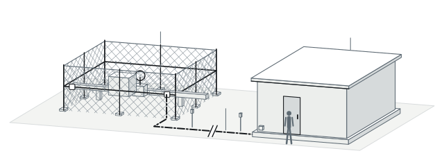
Pull Active Electronics up to 20 km Back to a Staffed Equipment Room

Pipeline block-valve cages, oil and gas wellheads, and booster pump stations often sit miles from staffed buildings where conditioned power and IT technicians are stationed. Because FO-750 uses low-loss 1,550 nm single-mode fiber rated at 0.24 dB/km, up to 20 km of non-sensing lead-in cable connects remote passive fence zones back to a central equipment room. Routine processor diagnostics stay safely indoors while remote boundaries carry only unpowered glass fiber.

Plan this perimeter →
Remote valve compound
Unstaffed Valve / Pump Compound010203
01
Unstaffed valve / pump compound
0 W fence
02
Non-sensing lead-in route · Up to 20 km
0.24 dB/km, 1,550 nm
03
Central equipment room
Indoor servicing
04 — Field deployment

Engineered for the boundary you operate.

Scenario 03 · Existing Fence Retrofit

Add Passive Optical Detection to Standing Fences Without Civil Rework

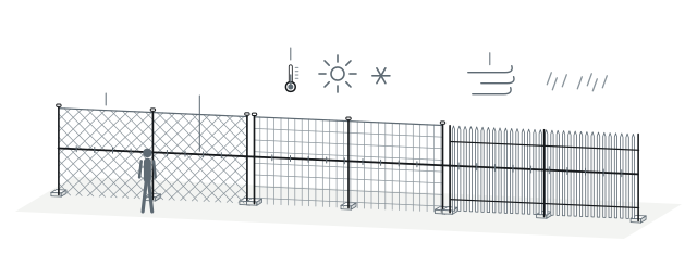
Replacing an intact perimeter fence just to gain intrusion alarms wastes capital budget and leaves live infrastructure exposed during demolition. FO-750 fastens a UV-resistant 12-core single-tube loose-tube 9/125 μm optical cable directly onto existing chain-link, welded-mesh, or steel palisade fencing across -40°C to +70°C climates. Adaptive environmental processing continuously suppresses wind and rain rattle while catching climbing and wire-cutting forces.

Plan this perimeter →
UV-resistant 12-core loose-tube 9/125 μm sensing cable
Chain-Link / Welded-Mesh / Palisade Fence01020304
01
Chain-link / welded-mesh / palisade fence
02
12-core loose-tube 9/125 μm cable
UV jacket
03
-40°C to +70°C outdoor rating
04
Adaptive wind and rain filtering
04 — Field deployment

Engineered for the boundary you operate.

Scenario 04 · High-EMI and Flammable Process Boundaries

Eliminate Spark, Surge, and EMI Risks Along Substation and Gas Fences

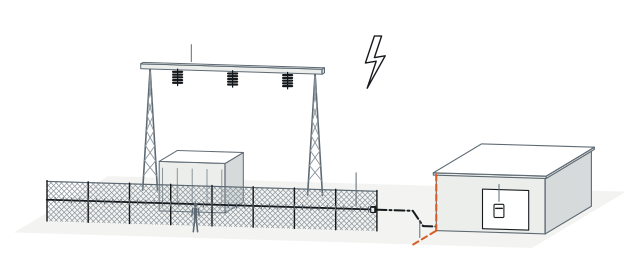
High-voltage switchyard switching arcs, direct lightning corridors, and flammable gas wellheads rapidly degrade active copper fence sensors and complicate hazardous-area wiring permits. FO-750 deploys non-conductive optical glass along the fence with zero electrical power, zero copper loops, and complete immunity to EMI and lightning surges. All powered circuitry remains cleanly isolated inside your safe-area control room.

Plan this perimeter →
Clean electrical separation for substations and gas facilities
HV Switchyard / Flammable Process Zone01020304
01
HV switchyard / flammable process zone
02
Dielectric glass fiber
EMI and lightning immune
03
Optical isolation boundary
04
Safe-area control cabinet
04 — Field deployment

Engineered for the boundary you operate.

Scenario 05 · Integrator Cabinet and Alarm Interfacing

Drop a 444 g, 2 W PoE Processor Straight onto Existing DIN Rails and NVRs

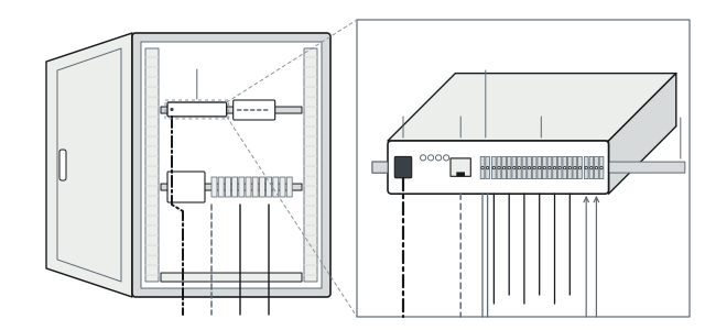
Small station RTU cabinets rarely have spare AC outlets, deep server shelves, or middleware servers for heavyweight security appliances. Weighing just 444 g in a 179 × 43 × 155 mm footprint, FO-750 mounts on DIN rails, racks, or outdoor enclosures and draws only 2 W via PoE or 12–48 VDC. Built-in Ethernet, 6 configurable Form C relays (1 A, 30 VDC), and 2 dry-contact inputs—all surge-protected—wire directly into NVRs and alarm panels.

Plan this perimeter →
FO-750 processor interface layout
179 × 43 × 155 mm010203040506
01
179 × 43 × 155 mm
444 g
02
SC/APC
1,550 nm sensing port
03
Built-in PoE Ethernet
04
12–48 VDC
2 W
05
6 Form C relays (1 A, 30 VDC) + 2 dry-contact inputs
06
DIN rail / rack / outdoor enclosure
05 — System architecture and bill of subsystems

0 W Passive Fiber on the Fence—One 2 W Processor in the Cabinet

Every PerimOptic FO-750 system separates 0 W outdoor optical zone hardware from a single 2 W processor—simplifying fence installation, long-distance lead-in routing, and control-room commissioning.
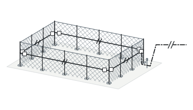
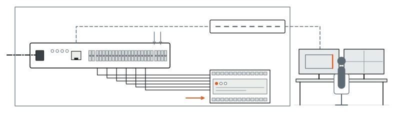
PASSIVE FIELD0 W (Unpowered)Mounted on perimeter fence fabric
Zone 01 / 02 / 03 / 04 · Up to 300 m Each
01
Zone 01 / 02 / 03 / 04 · Up to 300 m each
Start → end, 0 W
02
Non-sensing lead-in fiber · Up to 20 km
0 W
POWERED BACKENDPoweredDIN rail, rack, or protective outdoor enclosure
SC/APC Optical Port
03
SC/APC optical port
1,550 nm
04
FO-750 processor
12–48 VDC or PoE · 2 W · Local buffer
05
PoE switch / VMS / alarm panel
06
6 configurable Form C relays (1 A, 30 VDC) + 2 dry-contact inputs

System components and trade interfaces

Subsystem Layer
Components Included
Power Status
Location and Trade Scope
01 · Fence Sensing Optical Cable
12-core single-tube loose-tube 9/125 μm single-mode optical cable (1,550 nm, 0.24 dB/km, UV-resistant jacket, -40°C to +70°C) across up to 4 zones × 300 m
0 W (Unpowered)
Mounted on perimeter fence fabric · Fence and fiber crew
02 · Zone Start and End Elements
Passive optical zone start and termination hardware defining each of the 4 independent detection zones along the perimeter
0 W (Unpowered)
Fence zone boundaries · Fiber splicing and termination crew
03 · Non-Sensing Lead-In Cable
Passive optical transmission cable (up to 20 km between processor SC/APC port and Zone 01 start element)
0 W (Unpowered)
Conduit, trench, or cable tray to control building · Fiber crew
04 · FO-750 Detection Processor
Compact interferometric processor (179 × 43 × 155 mm, 444 g) with PoE Ethernet, local alarm buffer, 6 Form C relays (1 A, 30 VDC), and 2 dry-contact inputs
Powered (12–48 VDC or PoE; 2 W)
DIN rail, rack, or protective outdoor enclosure · SI commissioning
06 — Technical specifications

PerimOptic FO-750 Full Engineering Specifications

Detection and Zoning
Parameter
Standard Specification
Sensing Principle
Interferometric optical fiber vibration detection; 0 W passive outdoor fence sensing
Detection Zones and Length
Up to 4 independent zones per processor; up to 300 m per zone
Detected Intrusion Events
Fence cutting, climbing, and structural attempts to damage supported fence types
Environmental Noise Rejection
Adaptive background-noise filtering reducing wind and rain effects; immune to EMI and lightning
Optical Interface and Cable
Parameter
Standard Specification
Non-Sensing Lead-In Distance
Up to 20 km (sensing optical cable simultaneously serves as alarm signal transmission cable)
Optical Port and Wavelength
SC/APC connector; 1,550 nm laser wavelength
Sensing Cable Construction
12-core single-tube loose-tube optical cable; 9/125 μm single-mode fiber; UV-resistant outer jacket
Optical Attenuation
0.24 dB/km at 1,550 nm
Electrical, Network and I/O
Parameter
Standard Specification
Input Voltage and Power
12–48 VDC or built-in PoE; 2 W power consumption
Network and Outage Continuity
Built-in PoE-capable Ethernet port; local alarm buffering inside processor during network interruption
Relay Outputs and Auxiliary Inputs
6 configurable Form C relay outputs (1 A at 30 VDC); 2 dry-contact inputs
Surge Protection
Integrated surge protection circuits across all inputs, outputs, and power terminals
Mechanical and Environmental
Parameter
Standard Specification
Processor Dimensions and Weight
179 × 43 × 155 mm (L × W × D, including mounting brackets and optical interface); 444 g
Mounting Options
DIN rail, equipment rack, or protective outdoor enclosure
Operating Temperature and Humidity
-40°C to +70°C (processor and sensing cable); 0–95% RH, non-condensing

Above values reflect standard product technical specifications. Lead-in optical loss budgets, 4-zone start/end layouts, and relay function assignments are finalized against your compound drawings during project design.

07 — Engineering FAQ

Common Questions Before Specifying FO-750

01How do we choose between FO-750 zoned fiber, FO-700 locating fiber, and VC-600 locating vibration cable?

Specify PerimOptic FO-750 for compact compounds needing 4 independent fence zones (up to 300 m each), 0 W EMI-immune boundary fiber, a 2 W PoE processor, and up to 20 km of non-sensing lead-in cable. Choose PerimOptic FO-700 when multi-kilometer fences or pipelines demand continuous meter-level locating, or choose PerimVibe VC-600 when upgrading up to 600 m of existing fencing with 3 m electronic locating.

02Does using up to 20 km of non-sensing lead-in fiber reduce the 300 m sensing length of each zone?

No—the up to 20 km non-sensing lead-in rating defines the transmission span from the processor SC/APC port to the zones, while each of the 4 detection zones independently supports up to 300 m of fence sensing cable. During design, our engineers verify your end-to-end splice and cable loss budget at 0.24 dB/km (1,550 nm).

03What happens to perimeter alarms if the station Ethernet link goes offline during a storm?

FO-750 buffers intrusion alarm messages locally inside the 2 W processor throughout the network interruption so event records remain intact upon reconnection. Simultaneously, the 6 onboard Form C relays (1 A, 30 VDC) continue triggering hardwired local sirens, strobes, or NVR alarm inputs without relying on IP traffic.

04How are sliding or swing vehicle gates protected on a 4-zone substation or valve site?

Each fence zone terminates cleanly at passive start/end hardware beside the gate posts. Across the movable gate opening itself, engineers typically pair the opening with a PerimWave MW-400 bistatic microwave link (5–200 m) or wire heavy-duty gate contacts directly into FO-750's 2 dry-contact inputs or the station alarm panel.

08 — Next step

Get a Preliminary FO-750 Zone Proposal and Equipment Supply Quote

Send us your compound dimensions and control-room location—even at an early planning stage. Our engineering team will map your 4 fence zones, calculate lead-in fiber routing, and prepare a complete equipment supply quotation.

01Lengths of each perimeter side (up to 4 zones × 300 m per processor) and gate locations
02Existing or planned fence structure (chain-link, welded-mesh, or steel palisade)
03Lead-in fiber distance (up to 20 km) between the perimeter and your equipment room
04Preferred power and reporting setup (PoE or 12–48 VDC; Ethernet or 6 Form C relays)
Substations ↗Oil and Gas Terminals ↗Solar and Battery Storage ↗Airports ↗How It Works ↗Power Planning Guide ↗Installation and Maintenance ↗Compare All Products ↗