Engineering Guide · Survey, ITP, SAT, and Maintenance Checklists
PIDS Installation, Commissioning, and Maintenance: A Project Checklist
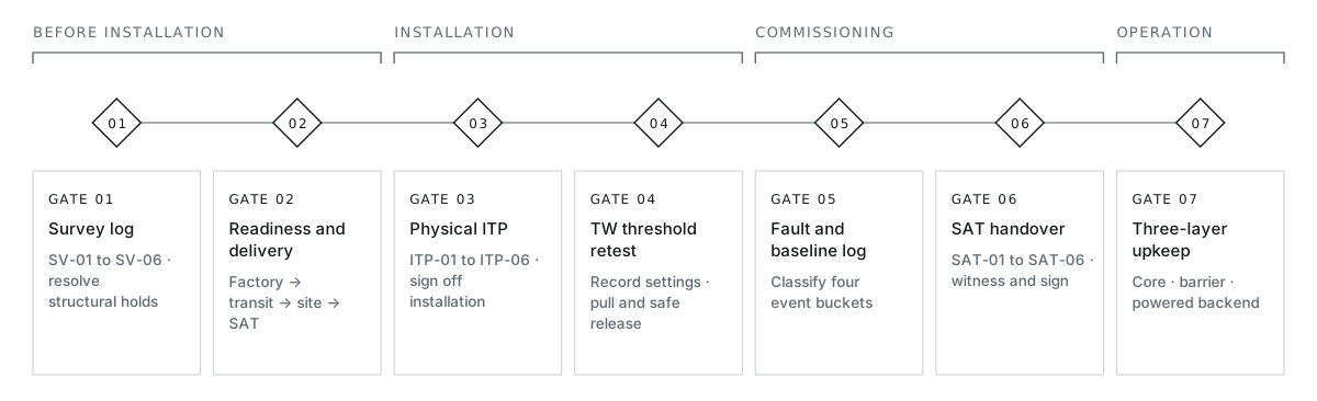
Reliable PIDS installation follows clear stage gates: structural survey, sensor mounting, commissioning tests and signed handover. Coordinate equipment supply, civil foundations, mechanical erection, head-end integration and maintenance across the project team, using the selected model manual for installation dimensions and wiring.
| Lifecycle Responsibility | Typical Party (Confirmed Per Project Contract) | Gate Condition Before Advancing |
|---|---|---|
| 01 · Equipment supply and product docs | PerimSense supplies agreed PIDS hardware BOM, preliminary zone layouts, and model manuals | Exact model codes, barrier format (TW-100 vs TW-150), and manual revision confirmed on order |
| 02 · Civil footings, walls, and conduits | Civil or fencing contractor executes foundations, wall copings, drainage frames, and cable ducts | Survey defects resolved; concrete cured and conduits proved clear before sensor mounting |
| 03 · Barrier and sensor erection | Fencing erector / installer mounts posts, wires/coils, optical cables, or buried/corridor units | Physical ITP inspection (#s03) passed—no loose posts or binding wires left to commissioning |
| 04 · Electrical, head-end, and SAT | System Integrator (SI) powers backend units, tunes settings, maps cameras, and leads witnessed tests | Threshold re-verification (#s04), fault injection, and baseline log (#s05) signed off at SAT (#s06) |
| 05 · Operations and layered upkeep | Facility security and grounds/electrical teams run SOPs, clear zones, and scheduled checks | As-built drawings, baseline settings archive, and 3-layer maintenance plan (#s07) handed over |
01 — Pre-construction site survey
Log Numbered Sector Conditions and Separate TW-100 vs TW-150 Checks
Walk every boundary sector before civil work starts. Assign sector IDs, attach dated photographs, and resolve any structural, clearance, or drainage defect that would compromise tensioning or detection.
| Survey Item ID | Boundary System Scope | What to Inspect and Record on Site | Photo / Drawing Ref | Defect Found and Remediation Owner | Hold-Point Status |
|---|---|---|---|---|---|
| SV-01 · Sector geometry, corners, and gates | All PIDS models | Sector start/end markers, length, grade steps, corner angles, sliding/swing gate widths, and vehicle crossing frequency | [Plan / Photo ID] | [Owner / Civil / Fence Contractor] | [Open / Cleared] |
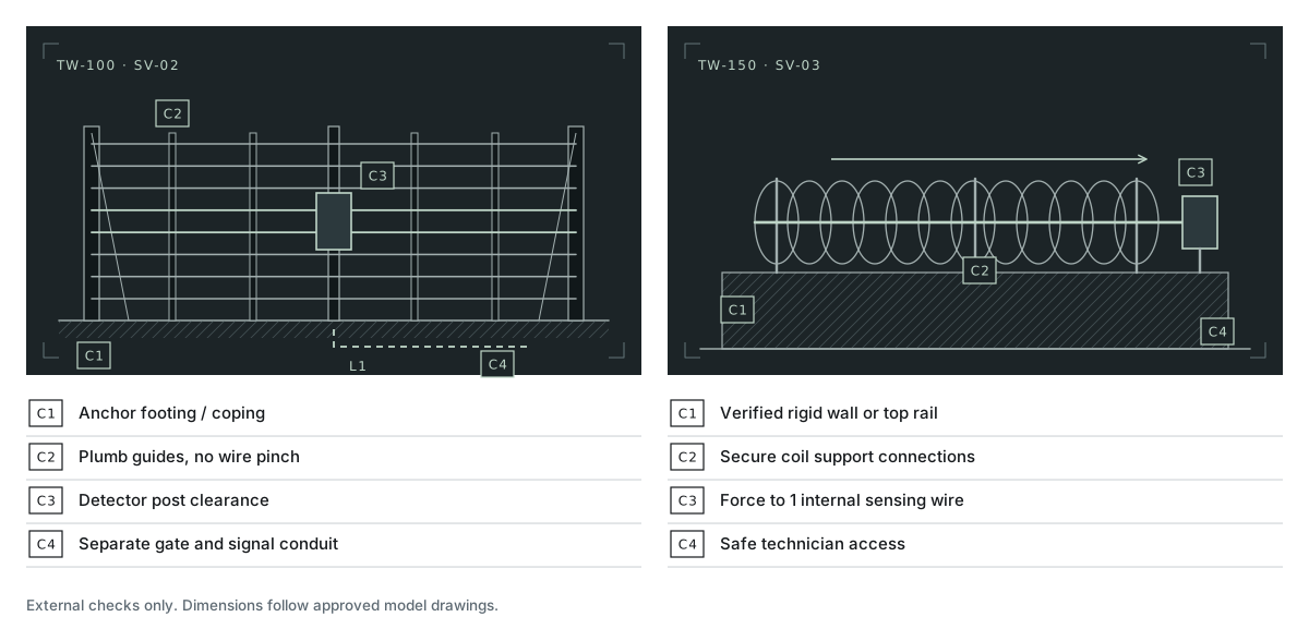
| SV-02 · Parallel taut-wire structural path | PerimTaut TW-100 | Soil bearing or wall-coping integrity for end/corner anchor posts, intermediate support line, gate-post terminations, and clear wire corridor | [Plan / Photo ID] | [Civil / Structural Engineer] | [Open / Cleared] |
| SV-03 · Concertina coil base and force transfer | PerimTaut TW-150 | Rigid wall coping or verified fence top rail, coil mounting/tie arrangement, axial load transfer to the 1 internal sensing wire per detector, and maintenance access | [Plan / Photo ID] | [Fence Contractor / PerimSense Review] | [Open / Cleared] |
| SV-04 · Host fence, surface, or corridor state | FF / FO / VC / BF / PM / EF / MW / LP | Mesh tension and loose panels (FO/VC); trench sub-base, drainage, buried utilities, and reviewed waterway depth/flow (BF-300) vs dry land paths (PM-280); flat unobstructed sightline (MW-400/MW-450M) | [Plan / Photo ID] | [Civil / Grounds / SI] | [Open / Cleared] |
| SV-05 · Electromagnetic exposure, vegetation, and wildlife | All PIDS models | Proximity to HV switchgear or electrified rail—where 0 W TW post switches and passive optical fibers operate unaffected by electromagnetic and radio-frequency interference (EMI/RFI)—plus overhanging branches, tall grass, and local wildlife activity | [Plan / Photo ID] | [Grounds / Electrical Eng] | [Open / Cleared] |
| SV-06 · Backend room, power, and head-end | All PIDS models | Protected indoor/enclosure space, AC/DC/PoE availability, earthing bar, conduit lead-in path (24-power-guide.html), camera presets, and existing alarm panel/VMS interface | [Plan / Photo ID] | [SI / Facility Electrical] | [Open / Cleared] |
02 — Pre-work readiness and delivery stages
Separate Hardware Dispatch from Site Readiness Across Four Stages
Fast equipment manufacturing shortens your critical path only when civil foundations, conduits, permits, and head-end interfaces are ready to receive the hardware. Track four separate delivery stages—and verify the pre-start readiness items before crews mobilize.
| Project Stage | Scope and Key Inputs | Pre-Condition to Enter Next Stage | Responsibility |
|---|---|---|---|
| Stage 01 · Factory Dispatch Readiness | BOM confirmation, barrier format selection, and factory production/testing (PerimTaut TW-100 and TW-150 support fast factory dispatch once configuration and order are confirmed) | Approved order BOM, model manual revision, and shipping consignee details locked | PerimSense + Buyer Procurement |
| Stage 02 · International Freight and Customs | Air/ocean transit, destination customs clearance, import documentation, and inland haulage to site | Packing list reconciled on arrival; enclosures and reels inspected for transit damage before storage | Freight Forwarder / Importer / Buyer |
| Stage 03 · Civil Works and Physical Mounting | Cured concrete footings/copings, pulled conduits, post erection, wire/coil tensioning or fiber splicing, and indoor backend wiring | Pre-Commissioning ITP (#s03) signed off with zero unresolved structural or cable defects | Civil / Fence Crew + SI |
| Stage 04 · Commissioning, Soak, and SAT | On-site threshold tuning, pull/cut and fault walk-tests, camera verification check, environmental soak log, and handover training | Witnessed SAT package (#s06) signed; unseasonable weather items logged for follow-up | SI + Facility Operations / Consultant |
03 — Pre-commissioning inspection (ITP)
Verify Mounting, Force Transfer, and Wiring Before Touching Any Threshold
Run this Inspection and Test Plan (ITP) sector by sector against approved drawings and the model manual. Verify secure posts, free wire movement, sound connections, and correct splices before powering processors and setting pull thresholds.
Scroll across for all fields; mobile shows labeled records.
| ITP Item ID | Physical or Electrical Check | Reference Basis | Result (Pass / Hold / N/A) | Sector / Photo Ref | Corrective Action Required | Re-Inspection Sign-Off |
|---|---|---|---|---|---|---|
| ITP-01 · Foundations, anchors, and brackets | End/corner anchors, wall-coping bolts, TW-150 coil brackets, or microwave posts are plumb, rigid, and fully cured | Approved civil/mounting drawing + model manual | [Pass / Hold] | [Sector / Photo] | [Re-anchor or brace before tensioning] | [Name / Date] |
| ITP-02 · Wire tension and clean force transfer | TW-100 parallel wires or TW-150 internal sensing wire move freely through guides without pinching, snagging, or foliage contact | Model installation manual for ordered version | [Pass / Hold] | [Sector / Photo] | [Clear pinch point / re-tension / trim brush] | [Name / Date] |
| ITP-03 · Host fence, grille, or trench finish | Attached FO/VC cables tied to tight mesh without slack loops; FF-250 grille frame secure; BF-300/PM-280 bedding reinstated | Model installation manual + civil spec | [Pass / Hold] | [Sector / Photo] | [Tighten mesh / secure ties / re-bed] | [Name / Date] |
| ITP-04 · Enclosures, glands, and splices | Detector post covers, junction boxes, and optical splice closures sealed; minimum bend radius respected; tamper switches seat cleanly | Model enclosure and cable schedule | [Pass / Hold] | [Sector / Photo] | [Replace seal / re-dress bend / re-splice] | [Name / Date] |
| ITP-05 · Power, earthing, surge, and labels | Indoor/cabinet supply voltages verified (P = V × I / ΔV within spec), SPD earthing bonded, and all L1/L2 cables labeled at both ends | Page 24 cable/load schedule + site electrical rules | [Pass / Hold] | [Rack / Cab ID] | [Correct polarity, SPD bond, or missing tags] | [Name / Date] |
| ITP-06 · Physical zone-to-camera alignment | Physical zone start/end posts match control-room zone map names, fence markers, and assigned camera fields of view | Approved zone map and VMS preset schedule | [Pass / Hold] | [Zone ID] | [Adjust preset angle or update zone label] | [Name / Date] |
04 — On-site adjustable pull threshold and re-verification
Log Pre/Post Pull Threshold Settings and Re-Test Both Contact Filtering and Intrusion Response
PerimTaut TW-100 and TW-150 feature an on-site adjustable pull threshold to filter out animal and plant contact. Follow three commissioning rules whenever pull thresholds are set or changed:
01
Record Mechanical Pull Settings
Follow the approved factory commissioning procedure for the supplied model version. Record the on-site adjustable pull threshold as mechanical pull transmitted to the sensing wire and detector.
02
Joint Re-Verification After Every Change
Any pull threshold adjustment to filter out animal and plant contact or wind-swayed foliage must be immediately followed by representative pull/spread and simulated-cut tests at the start, middle, and end of the zone to confirm target intrusion detection still passes.
03
Safe Cut Simulation
Verify wire or coil cut detection using the manufacturer-approved, site-authorized non-destructive release/test procedure, keeping active barrier wires and coils intact. Record barrier sensing-wire release tests separately from signal-cable open/short fault tests.
Scroll across for all fields; mobile shows labeled records.
| Project / Zone ID | Model and Manual Rev | Initial / Adjusted Setting Record | Date, Time, and Site Conditions | Approved Test Method and Positions / Trials | Expected Intrusion or Fault Output | Actual Control-Room Display and Camera Call-Up | Result (Pass / Hold) | Root Cause / Corrective Action and Retest | Performer and Witness Sign-Off |
|---|---|---|---|---|---|---|---|---|---|
| [e.g., Z-A01] | TW-100 · [Rev] | Pre: [Ref] → Post: [Ref] | [Date/Time · Wind / Temp / Grass] | Controlled pull test at start, mid, end (3 trials each) | Zone A01 Intrusion Alarm + Preset P-01 | [Log timestamp, zone ID, camera view] | [Pass / Hold] | [If Hold: fix binding/setting + retest] | [SI / Owner Rep] |
| [e.g., Z-A01] | TW-100 / TW-150 · [Rev] | Post-adjustment active baseline | [Date/Time · Ambient state] | Authorized non-destructive tension-release (cut simulation) | Zone A01 Intrusion/Cut Alarm | [Log timestamp and reset check] | [Pass / Hold] | [Verify clean mechanical return + retest] | [SI / Owner Rep] |
| [e.g., Z-A01] | Backend Module · [Rev] | Supervised / Tamper loop | [Date/Time] | Detector cover tamper open + L1-Mech cable disconnect test | Distinct Tamper / Line Fault (separate from wire pull) | [Log fault channel on head-end] | [Pass / Hold] | [Check EOL/wiring mapping + retest] | [SI / Owner Rep] |
05 — System linkage and environmental baseline log
Record Operating Events and Refine Performance
01
Record Site Test Results
Log successful detections against valid trials under the recorded conditions, such as 9/9 pulls on Zone A01. Keep the test method, conditions and results together for acceptance and future comparison.
02
Agree Four Event Categories
Record (1) Verified Intrusion/Test Events, (2) Environmental or Operational Non-Intrusion Triggers (wind, wildlife, adjacent traffic, staff activity), (3) Equipment/Power/Cable Faults, and (4) Unclassified Events awaiting camera/patrol review. Compare FAR/NAR using consistent denominators, zone lengths, and weather records.
03
Schedule Seasonal Verification
Include high winds, heavy storms and peak vegetation growth in the follow-up plan, with observations recorded against the commissioning baseline.
Scroll across for all fields; mobile shows labeled records.
| Observation Window and Active Uptime | Actual Weather and Site Operations Observed | Alarm Timestamp and Zone / Coordinate | Event Category (Intrusion / Env-Op / Fault / Unclassified) | Verification Evidence (Camera Clip / Patrol Note) | Responder Action Taken | Any Setting Change (Requires #s04 Retest!) | Unobserved Conditions / Follow-Up Item |
|---|---|---|---|---|---|---|---|
| [Start–End Dates · Total Active Hours] | [e.g., Moderate wind, HV switching, 12 truck gate cycles/day, night patrol] | [Timestamp · Zone ID or m] | [Select 1 of 4 categories; keep unknown cause as Unclassified] | [Camera ID / clip ref / guard report] | [Dispatched / Logged only / Work order] | [None, or log old→new + retest ref] | [e.g., Gale-force wind and monsoon rain check scheduled for Q3] |
06 — Site acceptance (SAT) and handover
Complete FAT and SAT Records for Signed Project Handover
Factory inspection verifies hardware before shipping. Site Acceptance Testing (SAT) verifies the installed barrier, field cabling, backup power, camera presets, and operator procedures together on your perimeter. Track remaining actions in the punch list and close them for handover.
| Handover Package Item | Required Deliverable Content | Verification Status (Accepted / Open Punch Item) | Responsible Owner | Sign-Off Role |
|---|---|---|---|---|
| SAT-01 · Project acceptance criteria | Agreed target events, zone/location tolerances, and fault tests matched to contract brief | [Accepted / Open] | Consultant / Owner Security | Owner / Consultant |
| SAT-02 · As-built drawings and cable tags | Final zone map, post/marker coordinates, L1/L2 cable routes, and enclosure power locations | [Accepted / Open] | System Integrator + Civil/Fence | SI / Facilities |
| SAT-03 · Baseline configuration archive | Final on-site TW threshold records, processor software/firmware versions, and backed-up settings | [Accepted / Open] | System Integrator | SI / Security Ops |
| SAT-04 · Signed ITP and test logs | Completed #s03 ITP sheets, #s04 pull/cut/fault test logs, and camera preset call-up verification | [Accepted / Open] | Installer + SI | Installer / SI / Owner |
| SAT-05 · Soak log and seasonal punch list | #s05 operational baseline log plus scheduled follow-up items for unobserved weather/seasons | [Accepted / Open] | SI + Security Operations | Owner Security |
| SAT-06 · Manuals, spares, and training | Approved manuals for supplied model revisions, agreed spare parts, and operator/grounds SOP walkthrough | [Accepted / Open] | PerimSense (docs/spares per BOM) + SI | Owner Facilities / Ops |
07 — Three-layer maintenance and symptom troubleshooting
Separate the Low-Upkeep Sensing Core from Routine Barrier and Backend Checks
On PerimTaut TW-100 and TW-150 barriers, core detection operates through the physical properties of its materials—so as long as its protective materials remain intact, the core sensing structure rarely suffers damage and needs minimal routine upkeep. Organize ongoing maintenance across three distinct layers, set check intervals from the product guidance and site exposure (coastal salt, dust, rapid vegetation growth), and always re-run affected zone walk-tests after storm damage, vehicle impact, civil/fence work, or setting changes:
| Maintenance Layer | What This Layer Covers | Routine Action and Trigger Condition | What to Log |
|---|---|---|---|
| Layer 01 · Core Sensing Structure (PerimTaut TW-100 / TW-150) | Material-property post sensing mechanism protected by its intact protective materials (0 W post switch) | Minimal core upkeep; check protective condition and function after physical impact or severe events using the maintenance guidance. | Visible external impact/damage, post-event functional check, and any item escalated to technical support |
| Layer 02 · External Barrier, Clear Zone, and Ground/Opening Hardware | Exposed tensioned wires or razor coils, anchor posts, fixings, host mesh (FO/VC), culvert grilles (FF-250), surface cover (BF-300/PM-280), microwave lanes (MW-400), and vegetation | Trim vegetation clear of wires/beams, clear culvert debris, inspect coastal/industrial corrosion, repair disturbed soil/paving, and retension wires where instructed | Sector ID, physical change found, remediation completed, and whether mandatory #s04 zone retesting was triggered |
| Layer 03 · Powered Backend, Batteries, and Reporting Chain | Zone modules, controllers, optical/active processors, UPS/standby batteries (MW-450M packs), surge earthing, network switches, and VMS/camera presets | Verify AC-fail/battery autonomy, clean optical connectors if opened, confirm software/setting baseline matches #s06 archive, and test alarm-to-camera handoff | Power/comm fault history, standby battery check result, firmware/setting version, and recovery walk-test sign-off |
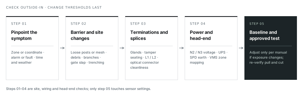
When contacting technical support for an installed system, include six items to speed diagnosis: (1) model code and manual/serial reference, (2) affected zone layout and connected backend hardware, (3) exact symptom and what changed on site beforehand, (4) exported alarm/fault logs, (5) clear site photographs, and (6) checks already run using Figure 25.3.