Home/Products/PerimTerra BF-300
PerimTerra BF-300 · Buried RF Electromagnetic Field Intrusion Sensor

Keep the Perimeter Completely Hidden. Pinpoint Every Breach to ±1 m.

Detect and locate intruders crossing open lawns, paved aprons, and shallow waterways without erecting a single visible post or fence. PerimTerra BF-300 projects an invisible 1 m high, 2–3 m wide RF field over 800 m per processor with ±1 m precision.
Share your site plan and ground media for a preliminary buried-route layout and equipment supply quote.
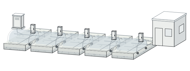
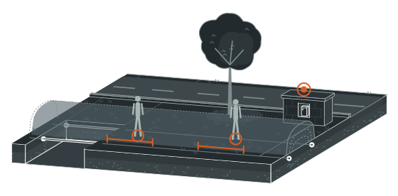
Up to 800 m per Processor (2 Cable Pairs)01020304
01Parallel buried cable pair (max spacing 2 m)
02Invisible volumetric RF field · 1 m high × 2–3 m wide
03Soil · Asphalt · Concrete · Shallow waterway
04BF-300 processor (<9 W · 12–48 VDC)
Up to 800 m per processor (2 cable pairs)
Exact Camera and Patrol Cueing
±1 m
Pinpoints single or simultaneous multi-intruder crossings along the route
Long-Span Processor Coverage
800 m
Protected per processor via 2 buried cable pairs (50–400 m lengths)
Invisible Above-Ground Corridor
1 m × 2–3 m
Typical volumetric RF field above parallel cables spaced up to 2 m
Shared Low-Power Backbone
<9 W
12–48 VDC processor draw letting up to 5 units share 1 power supply
01 — Key capabilities

Twelve Reasons High-Security Sites Bury BF-300 Along the Boundary

01

Conceal the Line Across Every Surface

01

Zero Visible Hardware

Conceal parallel sensing cables underground so intruders cannot spot or jump the line.

02

3 Ground Media Ready

Bury cables directly beneath soil, asphalt, and concrete without breaking perimeter continuity.

03

Shallow Waterway Crossings

Extend continuous buried RF protection right across shallow streams and drainage channels.

04

Terrain-Following Envelope

Track undulating hills and grade shifts with a 1 m by 2–3 m field.

02

Pinpoint Intruders Amid Harsh Weather

05

±1 m Location Precision

Pinpoint every perimeter crossing within ±1 m to steer PTZ cameras instantly.

06

800 m Per Processor

Monitor up to 800 m using 2 cable pairs across 50–400 m standard lengths.

07

Multi-Intruder Tracking

Locate multiple simultaneous intruders independently during coordinated perimeter breaches.

08

Conductivity-Size-Speed Filtering

Evaluate target conductivity, size, and speed while ignoring wind, rain, vegetation, and vibration.

03

Harden Field Power and Fiber Networking

09

<9 W Shared Power

Draw <9 W at 12–48 VDC and run up to 5 processors per supply.

10

3-Point Tamper Supervision

Trigger immediate tamper alarms on cable cuts, processor interference, or enclosure opening.

11

4 Form C Relays Onboard

Drive local interfaces via 4 relays (0.125–10 s) plus +8 relay/input cards.

12

Up to 10 km Fiber Links

Network processors over RS-422 (1.2 km), multimode (2.2 km), or 1,310 nm fiber (10 km).

02 — Operating principle

How Buried Parallel Cables Turn Open Ground into a ±1 m Locating Corridor

Each BF-300 processor drives 2 pairs of parallel buried coaxial sensing cables spaced up to 2 m apart beneath soil, asphalt, concrete, or shallow waterways.
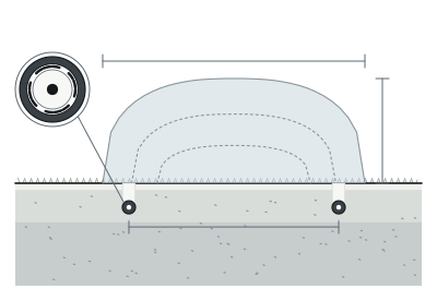
Active Buried RF Corridor1 m × 2–3 m≤2 m
01
Active buried RF corridor
Cable spacing ≤2 m · Field 1 m high × 2–3 m wide
Target Signature Discrimination
02
Target signature discrimination
Conductivity + size + speed (rejects weather / seismic noise)
±1 m Multi-Target Reporting
03
±1 m multi-target reporting
Up to 800 m / processor · Relays / RS-422 / fiber

Together, the transmit and receive cables establish an invisible volumetric RF electromagnetic field typically 1 m high and 2–3 m wide above the surface across up to 800 m per processor.

When an intruder enters this corridor, the processor analyzes the disturbance by electrical conductivity, physical size, and movement speed—rejecting vegetation sway, heavy weather, and ground vibration—before reporting single or simultaneous intrusion positions to within ±1 m via onboard Form C relays, RS-422, or fiber networks.

03 — Concealed boundary certainty

Zero Visible Posts Along 800 m—Yet Operators Pinpoint Intrusions Within ±1 m.

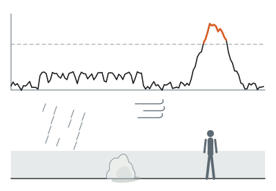
Security directors hesitate to bury perimeter sensors for two reasons: seismic ground cables scream false alarms whenever trucks rumble past or storms lash tree roots, while unlocated buried zones leave guards searching hundreds of meters of dark lawn in vain.
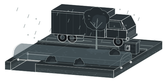
Ignored Outdoor Disturbances
Left
Ignored outdoor disturbances
Grass, shrubs, trees + wind, rain, snow + ground vibration
Baseline stable · 0 nuisance dispatch
Verified Multi-Point Intrusion (800 m Span)
Right
Verified multi-point intrusion (800 m span)
1 m × 2–3 m volumetric field · Target conductivity + size + speed
2 simultaneous alarms located within ±1 m

BF-300 solves both by sensing volumetric electromagnetic field changes above ground rather than mechanical soil vibration—making it immune to road tremor, acoustic noise, blowing debris, snow, and deep-rooted vegetation.

When one or several intruders enter its 1 m high, 2–3 m wide corridor across an 800 m processor span, the processor pinpoints every crossing within ±1 m so PTZ cameras lock straight onto the target.

04 — Field deployment

Engineered for the boundary you operate.

Scenario 01 · Open Lawns and Private Estates

Preserve Unbroken Landscape Sightlines While Guarding Every Approach

Perimeter fences and sensor posts slice across manicured lawns and garden vistas, turning a private estate or diplomatic residence into an industrial compound. BF-300 buries its sensing cable pairs completely out of sight, projecting an invisible 1 m high, 2–3 m wide RF corridor that rises and falls smoothly with rolling terrain. Security teams receive ±1 m breach coordinates long before an intruder reaches residence doors, while lawns and views remain untouched.

Plan this perimeter →
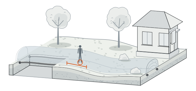
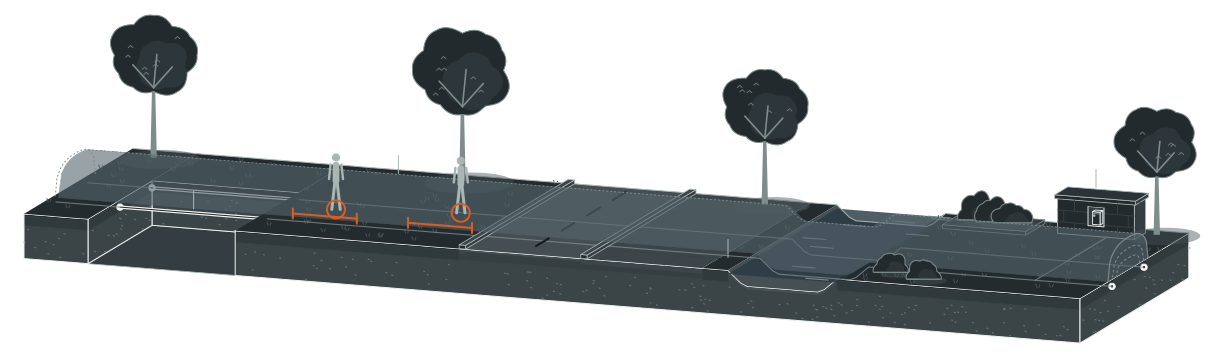
Estate lawn cross-section
Unobstructed Estate Sightline
Unobstructed estate sightline
Undulating lawn terrain
Concealed RF corridor
1 m × 2–3 m
±1 m intrusion cue before building approach
04 — Field deployment

Engineered for the boundary you operate.

Scenario 02 · Multi-Surface and Waterway Crossings

Carry One Unbroken Detection Line Under Asphalt, Concrete, and Streams

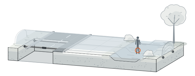
Real site boundaries cross paved driveways, concrete aprons, and shallow drainage creeks—leaving awkward surface transitions where single-medium sensors stop short. BF-300 routes standard 50, 100, 150, 200, 300, and 400 m cable sections continuously beneath soil, asphalt, and concrete, and extends directly across shallow waterways. Intruders wading a boundary stream or crossing a paved service road encounter the exact same monitored perimeter without dead gaps.

Plan this perimeter →
Multi-media boundary continuity
Turf and Native Soil
Turf and native soil
Asphalt / concrete paved crossing
Shallow waterway / stream crossing
Continuous cable sections
50–400 m
04 — Field deployment

Engineered for the boundary you operate.

Scenario 03 · High-Security Sterile Buffer Strips

Add a Concealed Second Layer That Tracks Simultaneous Intruders

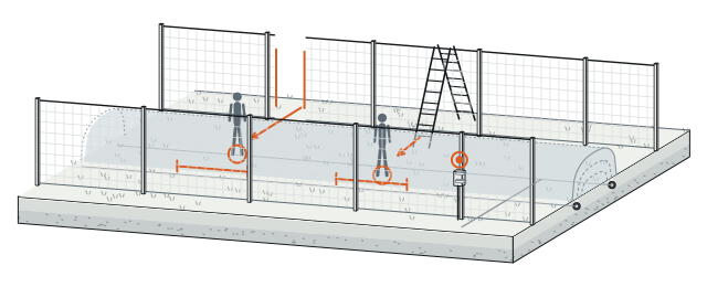
If an attacker bridges or cuts an outer fence during a coordinated diversion, security operators need to know immediately where each person lands on the inner ground strip. Buried inside the sterile buffer strip (spaced up to 2 m), BF-300 covers up to 800 m per processor and locates multiple simultaneous intruders to within ±1 m. Tamper supervision immediately flags any attempt to dig up cables or pry open the -40°C to +70°C field processor.

Plan this perimeter →
Double-fence sterile buffer strip
Outer Perimeter Fence
Outer perimeter fence
Sterile buffer strip
Cable spacing ≤2 m
Simultaneous breach A and breach B
±1 m
Inner fence + processor
-40°C to +70°C · 800 m
04 — Field deployment

Engineered for the boundary you operate.

Scenario 04 · Cultural Landmarks and Historic Grounds

Guard Monument Perimeters Without Altering Historic Architecture

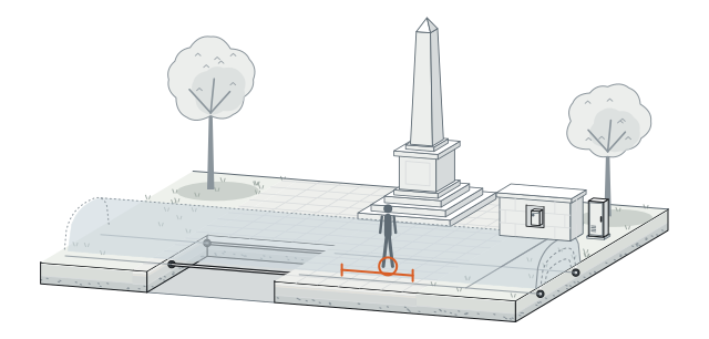
Historic palaces, archaeological parks, and landmark museums welcome thousands of daytime visitors, leaving exterior grounds exposed after closing while heritage rules forbid visible security cages. BF-300 hides sensing cables beneath existing turf and stone-paved plazas, placing compact 400 × 235 × 165 mm (4.9 kg) processors—or optional 984 × 425 × 273 mm protective cabinets—inside discreet utility niches. Nighttime security staff gain ±1 m perimeter awareness with 0 above-ground sensor posts along the protected monument line.

Plan this perimeter →
Heritage grounds perimeter
Historic Grounds / Cultural Monument Zone
Historic grounds / cultural monument zone
0 above-ground posts along buried route
Processor
400 × 235 × 165 mm (4.9 kg)
Optional protective cabinet
984 × 425 × 273 mm
04 — Field deployment

Engineered for the boundary you operate.

Scenario 05 · Multi-Kilometer Power and Fiber Integration

Share Power Across 5 Processors and Chain Sites Over 10 km Single-Mode Fiber

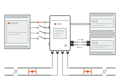
Trenching dedicated AC mains and lightning-prone copper data lines to every field processor drives civil budgets sky-high on multi-kilometer perimeters. Each BF-300 processor consumes <9 W from 12–48 VDC so up to 5 processors share 1 common power supply, protected by transient suppression diodes and gas discharge arrestors on every port. Integrators link standalone or networked units via 4 onboard Form C relays (0.125–10 s), 2 configurable inputs, +8 relay/input cards, RS-422 (1.2 km), 820 nm multimode fiber (2.2 km), or 1,310 nm single-mode fiber (10 km).

Plan this perimeter →
Multi-processor power and communication architecture
1 Common Supply (12–48 VDC) → Up to 5 Processors (<9 W Each)
1 common supply (12–48 VDC) → up to 5 processors (<9 W each)
Onboard 4 Form C relays (0.125–10 s) + 2 inputs
Optional +8 relay card / +8 supervised input card
RS-422 (1.2 km) · 820 nm MMF (2.2 km) · 1,310 nm SMF (10 km)
05 — System architecture and bill of subsystems

From Buried Coaxial Cable Pairs to Control-Room Alarm Assessment

A PerimTerra BF-300 perimeter combines passive-looking underground RF cable pairs with low-power (<9 W) field processors and flexible relay, copper, or fiber reporting—allowing standalone 800 m coverage or continuous multi-processor perimeters.
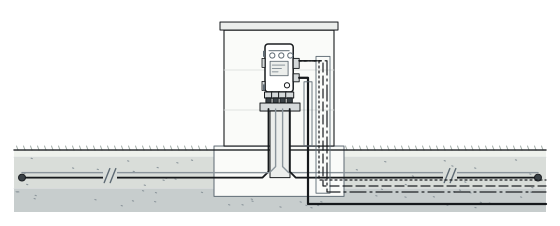
FIELD ASSEMBLYBuried beneath soil, asphalt, concrete, or shallow waterways
Side A Cable Pair (Up to 400 m) + Side B Cable Pair (Up to 400 m) = 800 m
01
Side A cable pair (up to 400 m) + side B cable pair (up to 400 m) = 800 m
02
BF-300 processor
4 TNC-F ports · 400 × 235 × 165 mm (4.9 kg)
03
Shared 12–48 VDC bus
<9 W / unit · Up to 5 processors
SECURITY MANAGEMENTPerimeter communication trench to security control room
A/B Tx/Rx Fiber Ring or Chain
04
A/B Tx/Rx fiber ring or chain
820 nm 2.2 km / 1,310 nm 10 km
05
4 onboard relays (+8 optional) / RS-422 (1.2 km)
06
Central alarm management and PTZ camera cue
±1 m

System components and trade interfaces

Subsystem Layer
Components Included
Power Status
Location and Trade Scope
01 · Buried Parallel Sensor Cable Pairs
2 pairs of direct-buried RF sensing cables per processor (50, 100, 150, 200, 300, or 400 m standard lengths; ≤2 m spacing; up to 800 m total)
RF-energized from BF-300 processor (4 TNC-F ports)
Buried beneath soil, asphalt, concrete, or shallow waterways · Civil trenching / slot cutting
02 · BF-300 Field Processor and Cabinet
400 × 235 × 165 mm (4.9 kg) outdoor processor with 4 TNC-F ports, 4 compression-gland entries, surge arrestors, and optional 984 × 425 × 273 mm cabinet
Powered (12–48 VDC, <9 W; up to 5 units per common supply)
Discreet boundary pedestal, niche, or protective cabinet · SI mounting and termination
03 · Onboard and Expansion Local I/O
4 Form C relays (1.0 A, 30 VDC, 0.125–10 s) + 2 self-test / dry-contact inputs; optional +8 Form C relay card and +8 universal input card
Powered internally by BF-300 processor
Inside processor chassis · Local dry-contact tie-in to RTU / NVR
04 · Network Communication Backbone
Optional RS-422 card (up to 1.2 km), 820 nm ST multimode fiber card (up to 2.2 km), or 1,310 nm 9/125 μm ST single-mode fiber card (up to 10 km)
Powered internally by BF-300 processor; control room on UPS
Perimeter communication trench to security control room · SI networking
06 — Technical specifications

PerimTerra BF-300 Full Engineering Specifications

Detection and Locating
Detection Principle
Active volumetric RF electromagnetic field around parallel buried sensing cables
Maximum Coverage per Processor
Up to 800 m per processor (2 sensing cable pairs per processor)
Intrusion Location Precision
Within ±1 m along the buried route; simultaneous multi-intruder locating supported
Typical Field Corridor and Spacing
Approximately 1 m high and 2–3 m wide above ground; maximum cable spacing 2 m
Target Discrimination and Immunity
Evaluates target conductivity, size, and speed; unaffected by grass, shrubs, trees, wind, rain, snow, hail, sandstorms, fog, seismic vibration, acoustics, or blowing debris
Buried Sensor Cables
Supported Ground and Water Media
Direct burial in most soil types, asphalt, and concrete; continuous routing across shallow waterways
Standard Detecting Cable Lengths
50 m, 100 m, 150 m, 200 m, 300 m, and 400 m
Tamper Protection
Immediate alarm on interference with sensing cables, processor, or enclosure
Electrical and Surge
Input Power and Consumption
12–48 VDC input; <9 W per processor (up to 5 processors may share 1 common power supply)
Port Lightning and Surge Protection
Transient suppression diodes and non-radioactive gas discharge devices on all I/O and power ports
Onboard I/O
Relay Outputs
4 Form C relays rated 1.0 A at 30 VDC; assignable functions; programmable activation time 0.125–10 s
Auxiliary / Self-Test Inputs
2 inputs (1 self-test input per cable side in standalone mode; programmable supervised dry-contact inputs in network mode)
Optional Expansion Cards
RS-422 Network Card
RS-422 communications up to 1.2 km
Multimode Fiber Network Card
ST connectors, 820 nm wavelength, A and B side Tx/Rx connections, up to 2.2 km
Single-Mode Fiber Network Card
ST connectors, 9/125 μm single-mode fiber, 1,310 nm wavelength, A and B side Tx/Rx connections, up to 10 km
Relay and Input Expansion Cards
8-channel Form C relay output card (1.0 A, 30 VDC); 8-channel universal input card with configurable thresholds and supervision
Mechanical and Environment
Processor Dimensions and Weight
400 × 235 × 165 mm (H × W × D); weight 4.9 kg
Connectors and Optional Cabinet
4 TNC-F bulkhead cable connectors + 4 waterproof compression-gland entries; optional telecom protective cabinet 984 × 425 × 273 mm
Operating Temperature and Humidity
-40°C to +70°C; 0–95% RH (non-condensing)

Above values reflect standard product technical specifications. Cable burial slot geometry, shallow-waterway anchoring, and shared 12–48 VDC voltage-drop budgets are matched to your project drawings during design.

07 — Engineering FAQ

Common Questions Before Specifying BF-300

01How does BF-300 differ from buried fiber-optic vibration systems like PerimOptic FO-700?

BF-300 generates an active 1 m high by 2–3 m wide RF electromagnetic corridor above ground, evaluating human conductivity, size, and speed for ±1 m locating up to 800 m per processor without relying on soil vibration—ideal for paved concrete/asphalt transitions and high-vibration road margins. Choose PerimOptic FO-700 when you need 0 W completely passive optical sensing over tens of kilometers (up to 100 km buried cable) with 15 m event resolution.

02For boundary creeks and culverts, when do we use BF-300 versus PerimGrille FF-250?

Use BF-300 to carry an open, barrier-free buried detection corridor continuously across shallow streams and landscaped waterways so the land-to-water perimeter has 0 gaps. When a deep culvert, drainage pipe, or submerged tunnel requires a physical anti-entry grate that stops swimming or crawling entry while detecting cutting and prying, pair that opening with PerimGrille FF-250 (60–80 mm deformation trigger).

03How are the 50–400 m standard cable lengths combined to reach 800 m on 1 processor?

Each BF-300 processor provides 4 TNC-F bulkhead ports to terminate 2 pairs of parallel sensing cables—typically one pair extending up to 400 m on Side A and one pair up to 400 m on Side B for 800 m total coverage. Shorter boundaries match 50, 100, 150, 200, or 300 m factory cable sets to your exact site segments.

04Can BF-300 integrate into an existing control room without laying new AC power along the perimeter?

Yes. Because each processor draws <9 W from 12–48 VDC, up to 5 processors (covering up to 4,000 m when chained across five 800 m spans) can share 1 low-voltage DC supply, while alarms and ±1 m locations return over onboard Form C relays, RS-422 (1.2 km), or 1,310 nm single-mode fiber up to 10 km.

08 — Next step

Get a Preliminary BF-300 Buried-Route Plan and Equipment Supply Quote

Send us your site boundary map, surface media breakdown, and control-room location. Our engineering team will segment 50–400 m cable pairs, place <9 W processors, and prepare a complete equipment supply quotation.

01Total concealed perimeter length and clear corridor width available (up to 2 m cable spacing)
02Surface breakdown along the route: soil/turf, asphalt, concrete, and any shallow waterway crossings
03Available 12–48 VDC power points (up to 5 processors per supply) and cabinet mounting preferences
04Preferred alarm backbone: dry-contact relays, RS-422 (1.2 km), multimode (2.2 km), or single-mode fiber (10 km)
Private Estates ↗Airports ↗Data Centers ↗Oil and Gas Terminals ↗How PIDS Works ↗Power Planning Guide ↗Installation and Maintenance ↗Compare All Products ↗