Home/Products/PerimWave MW-400
PerimWave MW-400 · Bistatic Volumetric Microwave Sensor

Turn Open Gates and Unfenced Gaps into Monitored Volumetric Zones.

Close vehicle gates, hangar aprons, and rooftop gaps where continuous fence sensors cannot cross. PerimWave MW-400 projects an invisible 5–200 m volumetric microwave field with digital target discrimination, automatic gain control, and 4 assignable Form C relays at 1.5 W Tx and 2.6 W Rx.
Share your gate spans, corridor widths, and mounting planes for a preliminary zone proposal and equipment supply quote.
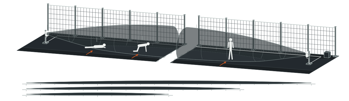
4 Assignable Form C Relays + Optional RS-422010203040506200 m150 m100 m
01All-digital transmitter (Tx · 1.5 W)
02All-digital receiver (Rx · 2.6 W)
03Spindle-shaped volumetric field
04Walking target · 5–200 m
05Crawling target · 5–150 m
06Prone movement · 5–100 m
4 assignable Form C relays + optional RS-422
Posture-Graded Corridor Span
5–200 m
Covers 200 m walking, 150 m crawling, and 100 m prone crossings
All-Weather Path Stability
DSP + AGC
Filters outdoor clutter and compensates for rain, fog, and span loss
Ultra-Light Power Budget
1.5 W / 2.6 W
Tx and Rx with comms card run on 12–48 VDC perimeter buses
Direct Panel Integration
4 Form C Relays
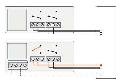
2 assignable relays per head (0.125–10 s) plus optional RS-422
01 — Key capabilities

Twelve Reasons Specifiers Close Perimeter Gaps with MW-400

01

Seal Open Approaches Without Physical Barriers

01

5–200 m Walking Coverage

Seal wide gates and open corridors with a single transceiver pair.

02

150 m Crawl / 100 m Prone

Grade link spacing precisely around low-profile crawling and prone intrusion threats.

03

Spindle Volumetric Field

Project an invisible three-dimensional microwave zone that defeats jump-over attempts.

04

Stackable and Cascadable

Stack pairs for extra height or cascade links along extended perimeters.

02

Hold Outdoor Stability Through Weather Shifts

05

Digital Target Discrimination

Separate real human crossing signatures from windblown rain and background clutter.

06

Automatic Gain Control

Compensate automatically for path-loss shifts across weather and link distance.

07

-40°C to +70°C Endurance

Maintain stable outdoor detection across freezing winters, desert heat, and 95% RH.

08

Full-Port Surge Protection

Shield power, data, and relay lines with TVS diodes and gas tubes.

03

Simplify Power Sizing and Panel Integration

09

1.5 W Tx / 2.6 W Rx Draw

Slash field power budgets across 12–48 VDC perimeter supply buses.

10

4 Relays (0.125–10 s)

Assign 2 Form C contacts at each head for direct alarm triggering.

11

Optional RS-422 A/B Card

Integrate cascaded microwave links over dual-side transmit and receive buses.

12

Multi-Plane ABS Mounting

Mount rugged UV-resistant enclosures on ground posts, walls, parapets, or roofs.

02 — Operating principle

How a Bistatic Volumetric Link Detects Every Crossing

An all-digital microwave transmitter radiates energy toward a matched receiver across an unobstructed corridor, establishing an invisible spindle-shaped volumetric field between the units.
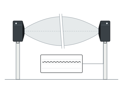
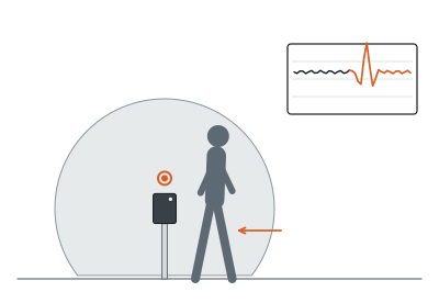
AGC-Stabilized Link
01
AGC-stabilized link
Normal operation
Digital Signature Check
02
Digital signature check
Human crossing
Assigned Alarm Output
03
Assigned alarm output
Alarm contacts
Separate signal paths

Automatic gain control continuously stabilizes receiver sensitivity against path-loss variations from link separation (5–200 m), site reflections, rain, and fog.

When a walking, crawling, or prone intruder enters the three-dimensional volume, phase and amplitude disturbances alter the received microwave envelope.

Digital signal processing evaluates that signature against background clutter and triggers the assigned Form C relays (0.125–10 s) or optional RS-422 A/B network bus.

03 — Outdoor stability and lightning resilience

Stop Rain Fade, Temperature Drift, and Conduit Surges from Disrupting Gate Coverage.

Open vehicle gates and exposed clear isolation corridors punish ordinary beam sensors with heavy rain attenuation, -40°C to +70°C thermal swings, and lightning surges coupled onto long outdoor cable runs.
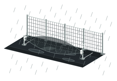
Weather and Span Path-Loss Shift
Weather and span path-loss shift
Automatic gain control (AGC)
Stable detection sensitivity
Background Environmental Effects
Background environmental effects
All-digital target discrimination (DSP)
Valid human crossing only
Induced Surge on Power / Data / Relay
Induced surge on power / data / relay
TVS diodes + gas discharge tubes
Protected 12–48 VDC electronics

MW-400 pairs automatic gain control with all-digital target discrimination: AGC dynamically offsets path-loss shifts across weather and link distance, while rule-based digital processing rejects background environmental effects before an alarm contact ever closes.

Every power, data, and relay terminal is guarded by transient suppression diodes and gas discharge tubes inside a UV-resistant ABS enclosure—keeping critical openings online without seasonal re-tuning.

04 — Field deployment

Engineered for the boundary you operate.

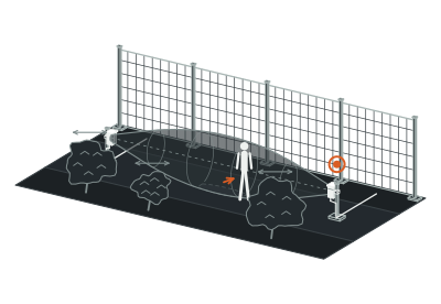
Scenario 01 · Vehicle Gates and Logistics Lanes

Seal Sliding and Swing Gate Openings Without Cutting Roadway Asphalt

Heavy truck gates interrupt fence-mounted fiber and taut-wire runs, leaving your widest entrance unmonitored whenever sliding leaves close for the night. Mounting an MW-400 pair across a 5–200 m gate corridor establishes an invisible volumetric barrier above the pavement without burying fragile cables in wheel ruts. 4 assignable Form C relays (rated 1.0 A at 30 VDC) tie directly into gate-status schedules and control-room camera presets.

Plan this perimeter →
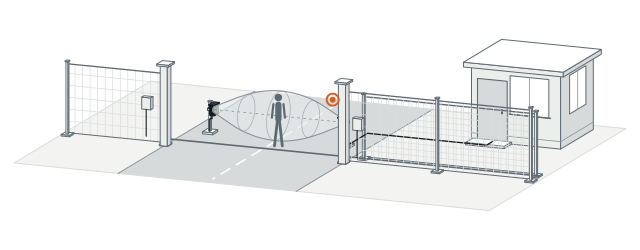
Gate gap closure
Fence Sensor Termination
Fence sensor termination
Sliding / swing gate leaf
MW-400 corridor
5–200 m
4 Form C relays
1.0 A, 30 VDC
04 — Field deployment

Engineered for the boundary you operate.

Scenario 02 · Aircraft Hangar Approaches

Guard Wide Hangar Aprons Where Physical Fences Cannot Cross Tow Paths

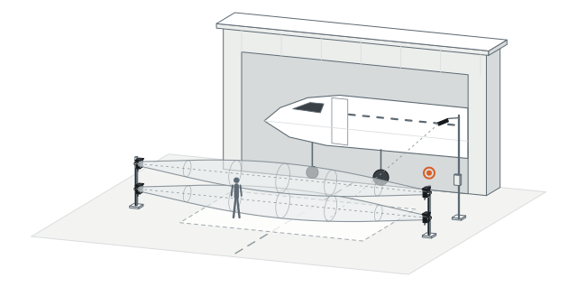
Open hangar aprons expose high-value aircraft across wide service approaches where tow tractors prohibit permanent gates or bollards. A single MW-400 link spans up to 200 m for upright walkers (150 m crawling, 100 m prone), projecting a defined alarm zone across the selected approach without obstructing tarmac operations. Where tall hangar doors demand higher vertical coverage, installers stack pairs cleanly on matching vertical masts.

Plan this perimeter →
Hangar service approach protection
Hangar Service Approach
Hangar service approach
Vertically stacked Tx / Rx masts
200 m walk / 150 m crawl / 100 m prone
PTZ assessment zone
04 — Field deployment

Engineered for the boundary you operate.

Scenario 03 · Rooftops, Walls, and Parapets

Catch Climbers Crossing Connected Roofs and Masonry Wall Tops

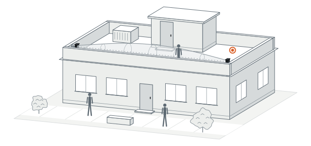
Securing ground-level fences means little if intruders climb an adjacent utility annex and walk across connected rooftops or wide parapet walls unchallenged. MW-400 mounts directly onto walls, wall tops, and flat roofs, turning elevated ledges into monitored corridors while keeping courtyards below open for daily staff traffic. Posture-graded spacing ensures low-crouching or prone intruders cannot belly-crawl beneath the beam undetected.

Plan this perimeter →
Elevated perimeter deployment
Parapet / Wall-Top Bracket
Parapet / wall-top bracket
Rooftop clear segment
Penthouse obstacle bypass
Unrestricted ground courtyard
04 — Field deployment

Engineered for the boundary you operate.

Scenario 04 · Clear Isolation Corridors

Add a Cascaded Volumetric Layer Inside Double-Fence Clear Corridors

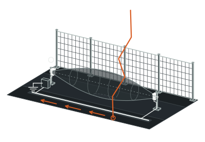
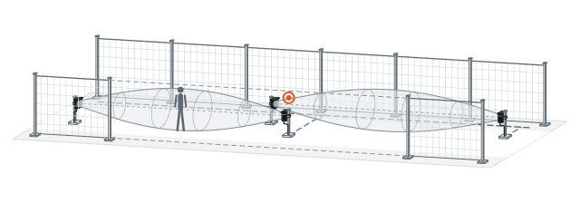
At nuclear, utility, and correctional perimeters, relying on a single fence sensor leaves zero second-layer confirmation once an outer mesh is breached. Cascading MW-400 pairs longitudinally down straight double-fence clear isolation corridors creates an independent volumetric detection zone that catches sprinting or crawling intruders immediately inside the outer line. Optional RS-422 A-side and B-side networking links multi-zone corridors cleanly while drawing just 1.5 W at Tx and 2.6 W at Rx.

Plan this perimeter →
Longitudinal cascading
Outer and Inner Perimeter Fences
Outer and inner perimeter fences
Clear isolation corridor
Longitudinally cascaded pairs
RS-422 A/B bus
1.5 W Tx / 2.6 W Rx
04 — Field deployment

Engineered for the boundary you operate.

Scenario 05 · Campus Internal Boundaries

Isolate Sensitive Labs and Vault Approaches Without Interior Cages

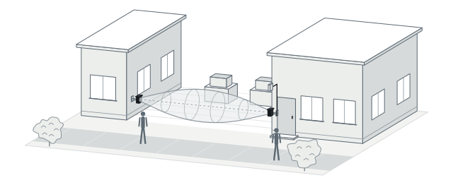
Research campuses and cultural institutions often share landscaped grounds where erecting interior razor-wire fences around test yards or collection annexes is unacceptable. Compact UV-resistant ABS MW-400 heads mount discreetly on building corners or low bollards to project an invisible security boundary across restricted walkways. Programmable relay hold times from 0.125 to 10 s ensure crisp alarm handshakes with existing access-control and VMS panels.

Plan this perimeter →
Discreet internal zoning
Public Campus Circulation
Public campus circulation
Wall-mounted MW-400 link
Restricted lab / vault boundary
0.125–10 s relay pulse to VMS
05 — System architecture and bill of subsystems

Every Hardware Element Required Across an MW-400 Corridor

PerimWave MW-400 is an active low-voltage bistatic microwave link: both the outdoor transmitter and receiver require 12–48 VDC power, while local Form C relays or optional RS-422 networking carry zone alarms to your control room.
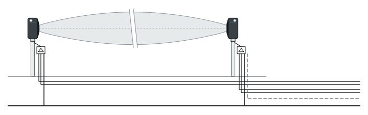
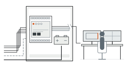
FIELD ASSEMBLY12–48 VDC · TX + RX
12–48 VDC Perimeter Power Bus
01
12–48 VDC perimeter power bus
02
MW-400 Tx
1.5 W · 2 Form C relays
03
5–200 m unobstructed spindle corridor
04
MW-400 Rx
2.6 W · 2 Form C relays + optional RS-422
05
TVS diodes + gas discharge tubes
All ports
SECURITY MANAGEMENT4 Form C · RS-422 A/B
RS-422 A-Side / B-Side Tx/Rx Bus
06
RS-422 A-Side / B-Side Tx/Rx bus
07
Control room alarm panel / VMS

System components and trade interfaces

Subsystem Layer
Components Included
Power Status
Location and Trade Scope
01 · Microwave Transmitter (Tx)
All-digital volumetric microwave transmitter in UV-resistant high-impact ABS housing with TVS + GDT surge protection and 2 assignable Form C relays
Powered (12–48 VDC, 1.5 W)
One end of clear corridor (ground, wall, parapet, or roof) · Low-voltage wiring
02 · Microwave Receiver (Rx)
All-digital volumetric microwave receiver with DSP target discrimination, AGC path-loss compensation, TVS + GDT surge protection, and 2 assignable Form C relays
Powered (12–48 VDC, 2.6 W with communications card)
Opposite end of 5–200 m clear corridor · Low-voltage and signal termination
03 · Optional RS-422 Network Card
Plug-in RS-422 communications card providing A-side and B-side Tx/Rx connections for multi-link networked integration
Powered via Rx chassis (included in 2.6 W rating)
Installed inside receiver enclosure · SI serial bus commissioning
04 · Mounting Brackets and Alarm Host
Ground, wall, wall-top, or stacked pole mounting hardware connected to site 12–48 VDC power bus and control-room alarm/VMS panel
Brackets 0 W; Host Powered (Site UPS)
Perimeter posts and indoor security room · Civil mounting and SI integration
06 — Technical specifications

PerimWave MW-400 Full Engineering Specifications

Detection Performance
Parameter
Standard Specification
Detection Principle
Bistatic volumetric microwave intrusion detection; all-digital transmitter (Tx) and receiver (Rx)
Detection Field Geometry
Invisible spindle-shaped three-dimensional volumetric field
Upright Walking Target Range
5–200 m
Crawling Target Range
5–150 m
Prone Movement Range
5–100 m
Signal Processing
All-digital target signature discrimination (DSP) + Automatic Gain Control (AGC) for path-loss compensation
Layout and Mounting
Parameter
Standard Specification
Boundary Extension Modes
Vertical stacking for increased zone height; longitudinal cascading for extended perimeter length
Supported Mounting Planes
Ground post, wall surface, wall-top (parapet), and rooftop mounting
Electrical and Power
Parameter
Standard Specification
Input Voltage Range
12–48 VDC
Transmitter (Tx) Power Consumption
1.5 W
Receiver (Rx) Power Consumption
2.6 W (with communications card installed)
Surge and Lightning Protection
Transient suppression diodes (TVS) and gas discharge tubes (GDT) on all power, data, and relay ports
Outputs and Networking
Parameter
Standard Specification
Relay Outputs
4 assignable Form C relays per pair (2 at Tx + 2 at Rx)
Relay Contact Rating
1.0 A at 30 VDC
Relay Activation Time
0.125–10 s, programmable
Optional Network Interface
RS-422 communications card with A-side and B-side Tx/Rx connections
Mechanical and Environmental
Enclosure Material
UV-resistant, high-impact ABS engineering plastic
Operating Temperature
-40°C to +70°C
Relative Humidity
0–95% RH, non-condensing

Above values reflect standard product technical specifications. Final link separation, clear-corridor grading, vertical stacking count, and relay/RS-422 mapping are matched to your site layout during design.

07 — Engineering FAQ

Common Questions Before Specifying MW-400

01Should we size our MW-400 corridor at 200 m, 150 m, or 100 m?

Size each link around the lowest intrusion posture your threat model requires. One MW-400 pair covers upright walking targets across 5–200 m, crawling targets across 5–150 m, and prone movement across 5–100 m; high-security double-fence clear isolation corridors typically space links within the 100 m prone rating.

02When should we choose fixed MW-400 versus portable MW-450M or EF-350 electrostatic sensing?

Specify MW-400 for permanent, straight line-of-sight openings such as vehicle gates, hangar aprons, rooftops, and clear isolation corridors wired to 12–48 VDC. Choose PerimWave MW-450M when you need tripod-mounted, battery-powered temporary cordons (30 h standby, ≥2,000 m wireless reporting), or PerimField EF-350 when a boundary follows tight curves and grade changes unsuitable for straight microwave beams.

03What site conditions are needed between the MW-400 transmitter and receiver?

MW-400 requires a straight, unobstructed line-of-sight corridor free of tall swinging vegetation, parked vehicles, and standing water puddles. At corners, curves, or grade breaks, links terminate cleanly and overlap into the next straight segment so no dead spot remains at the post base.

04How do the 4 Form C relays and optional RS-422 card wire into an existing fence alarm system?

Each MW-400 pair provides 2 assignable Form C relays at the transmitter and 2 at the receiver (1.0 A at 30 VDC, 0.125–10 s hold time), allowing direct dry-contact wiring into nearby PerimTaut TW-100 zone modules, PerimOptic I/O panels, or third-party PLC/VMS inputs. Multi-corridor sites can add the optional RS-422 A/B communications card for bus-level integration.

08 — Next step

Get a Preliminary MW-400 Gap-Closure Plan and Equipment Supply Quote

Send us your gate widths, open corridor dimensions, or rooftop layout. Our engineering team will size link separations for your target posture, check stacking or cascading overlaps, and prepare an equipment supply quotation.

01Each open span length (within 5–200 m) and clear corridor width available
02Target detection posture required: walking (200 m), crawling (150 m), or prone (100 m)
03Mounting plane: ground post, masonry wall, parapet top, or flat rooftop
04Available 12–48 VDC power points and preferred alarm interface (Form C relays or RS-422)
Airports ↗Substations ↗Oil and Gas Terminals ↗Data Centers ↗Commercial and Logistics ↗How Perimeter Sensing Works ↗Power Planning Guide ↗Installation and Maintenance ↗Compare All Products ↗