Home/Products/PerimField EF-350
PerimField EF-350 · Low-Frequency Electrostatic Volumetric Field Sensor

Build a Tall, Narrow Detection Wall Right on the Boundary Line.

Detect intruders approaching, climbing, or bridging fences, walls, and rooftops without spilling nuisance alarms into adjacent walkways. PerimField EF-350 projects a non-shocking electrostatic field across 2 × 150 m zones, scaling up to 7.3 m high with 50/60 Hz grid immunity.
Share your wall, rooftop, or fence profile for a preliminary wire-array layout and equipment supply quote.
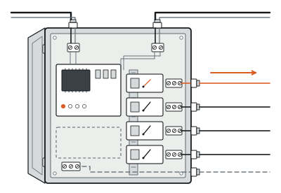
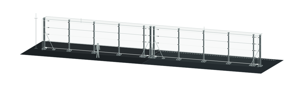
Zone A (150 m) + Zone B (150 m) · IP66 Processor (<6 W)010203
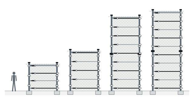
014 wires (2.45 m) · 5 wires (3.65 m) · Stacked 10 wires (7.3 m)
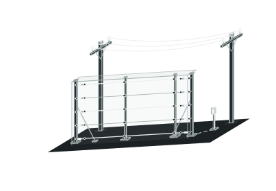
02Parallel field wires + sense wires (non-shocking)
03Tall, narrow volumetric field (≤0.5 m walk-up width)
Zone A (150 m) + Zone B (150 m) · IP66 processor (<6 W)
Vertical Anti-Climb Reach
Up to 7.3 m
Stackable fence arrays up to 7.3 m (up to 6.1 m freestanding or wall-top)
Dual-Zone Processor Span
2 × 150 m
Zone A and Zone B monitored from 1 IP66 processor (<6 W)
Substation-Ready Stability
50/60 Hz
Native power-grid immunity paired with enhanced DSP filtering
Verified Crossing Catch
95%
Detection probability for ≥35 kg upright intruders moving at 5 cm/s–8 m/s
01 — Key capabilities

Twelve Engineering Reasons Tight Perimeters Specify EF-350

01

Hug the Boundary Without Spilling Over

01

≤0.5 m Contained Width

Keep sensing within ≤0.5 m walk-up width so nearby lanes stay open.

02

Up to 7.3 m Fence Height

Stack fence-mounted arrays from 2.45 m (4-wire) up to 7.3 m (10-wire).

03

4 Mounting Profiles

Deploy freestanding, fence-mounted, wall-top (up to 6.1 m), or rooftop wire arrays.

04

Terrain-Following Wire Spans

Track rising and falling ground grades without leaving dead under-beam gaps.

02

Catch Intruders and Ladders Near Power Grids

05

Approach and Crossing Alarms

Detect field disturbances before an intruder finishes climbing or penetrating wires.

06

Tall Metal Target Catch

Trigger immediate alarms when metal ladders or poles enter the electrostatic field.

07

50/60 Hz Grid Immunity

Operate reliably beside high-voltage switchyards immune to 50/60 Hz hum.

08

95% Crossing Detection

Catch ≥35 kg upright intruders moving at 5 cm/s–8 m/s with 95% probability.

03

Run Dual Zones Under 6 W

09

2 × 150 m Per Processor

Monitor Zone A and Zone B up to 150 m each from 1 unit.

10

<6 W Ultra-Low Power

Power each IP66 processor (-40°C to +70°C) from 12–48 VDC at <6 W.

11

4 Fail-Safe Form C Relays

Provide 4 programmable 0.125–10 s fail-safe relays plus 2 supervised inputs.

12

RS-422 and +8 I/O Cards

Expand integration with A/B RS-422 networking, +8 relays, and +8 inputs.

02 — Operating principle

How Parallel Field and Sense Wires Detect Intrusion Without Electric Shock

EF-350 energizes insulated parallel field wires alongside passive sense wires to establish a controlled, non-shocking low-frequency electrostatic field along the perimeter.

Unlike contact-only wires or wide microwave lobes, this volumetric field wraps tightly around the wire array—within a ≤0.5 m walk-up width—and scales from 4-wire (2.45 m) and 5-wire (3.65 m) zones up to 7.3 m stacked fence arrays.
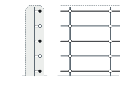
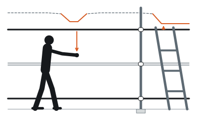
Non-Shocking Parallel Wire Field
01
Non-shocking parallel wire field
Field wires + sense wires · ≤0.5 m contained width
Approach or Penetration Disturbance
02
Approach or penetration disturbance
≥35 kg person (5 cm/s–8 m/s) or tall metal object
DSP Filtering and Zone Output
03
DSP filtering and zone output
50/60 Hz grid immunity · 4 fail-safe relays / RS-422

When an upright person (≥35 kg moving from 5 cm/s creeping to 8 m/s sprinting) or a tall metal object approaches or crosses the array, capacitive field coupling shifts; enhanced DSP algorithms filter weather stimuli while rejecting 50/60 Hz grid hum to trigger a verified zone alarm.

03 — Tight-corridor discipline

Confine Sensing Within a ≤0.5 m Narrow Zone—Zero Neighbor Trips, Zero Shock Risk.

Urban data centers, substations, and industrial yards rarely have wide buffer strips: patrol trucks, maintenance crews, and public sidewalks pass right beside the perimeter wall, causing wide-beam sensors to nuisance-alarm constantly while high-voltage electric fences create legal and safety liabilities.

EF-350 solves both constraints with a safe, non-shocking low-frequency electrostatic field held tightly around its parallel wires (walk-up width ≤0.5 m for a ≥35 kg person).
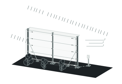
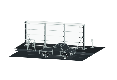
EF-350 Contained Field
EF-350 contained field
≤0.5 m walk-up width · Non-shocking
Adjacent Patrol Lane / Sidewalk Outside Field
Adjacent patrol lane / sidewalk outside field
Adjacent circulation
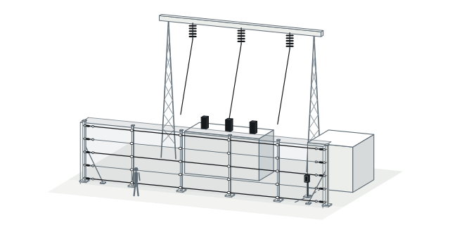
Overhead 50/60 Hz Power Lines → Immune
Overhead 50/60 Hz power lines → immune
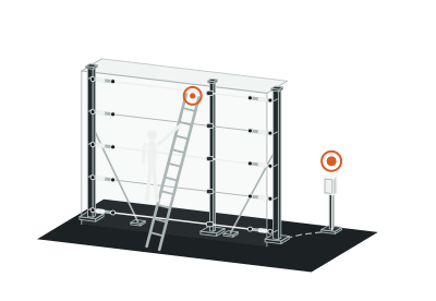
Intruder Approach / Metal Ladder → Immediate Alarm
Intruder approach / metal ladder → immediate alarm
Non-contact disturbance

Enhanced DSP algorithms strip away rain and wind noise while native 50/60 Hz immunity blocks power-grid hum—so routine traffic outside the narrow field moves freely while boundary approaches trigger decisive alarms.

04 — Field deployment

Engineered for the boundary you operate.

Scenario 01 · Existing Masonry and Concrete Walls

Catch Climbers and Ladders Above Solid Walls Before They Drop Inside

Solid masonry walls block outside views, yet intruders prop aluminum ladders against the coping and vault into the yard before inner cameras react. Mounted on insulated wall-top brackets (supporting wall/freestanding heights up to 6.1 m), EF-350 wraps the upper wall edge in a narrow electrostatic curtain that senses approaching bodies and tall metal ladders alike. Because the field is non-shocking, facilities upgrade wall security cleanly beside public streets.

Plan this perimeter →
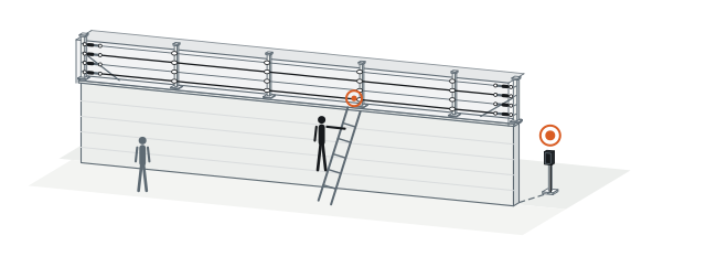
Wall-top array upgrade
Existing Masonry Boundary Wall
Existing masonry boundary wall
Wall-top insulated bracket
Up to 6.1 m config
4-wire / 5-wire non-shocking field array
Approaching climber / tall metal ladder detected
04 — Field deployment

Engineered for the boundary you operate.

Scenario 02 · High-Security Fence Stacking

Scale Vertical Coverage Up to 7.3 m Along Critical Perimeter Fences

High-security compounds, ports, and border facilities erect tall perimeter fences where standard single-tier toppers leave upper or lower sections exposed to cutting and pole-vaulting. EF-350 stacks modular wire arrays directly onto fence structures: 4 wires cover 2.45 m, 5 wires cover 3.65 m, 9 wires reach 6.8 m, and 10 wires deliver 7.3 m of continuous vertical field height. Upright intruders ≥35 kg crossing between 5 cm/s and 8 m/s are detected with 95% probability.

Plan this perimeter →
Fence-mounted vertical height progression
4 Wires2.45 m3.65 m6.8 m7.3 m
4 wires
2.45 m
5 wires
3.65 m
9 wires · 6.8 m
Stacked
10 wires
7.3 m max fence height
04 — Field deployment

Engineered for the boundary you operate.

Scenario 03 · Substations and Power Infrastructure

Eliminate 50/60 Hz Grid Hum Alarms Around High-Voltage Yards

Overhead busbars, step-up transformers, and underground feeder cables bathe substation boundaries in intense 50 Hz and 60 Hz electromagnetic fields that blind ordinary capacitive sensors. EF-350 is engineered for native immunity to 50/60 Hz power-grid interference and protects every processor I/O port with transient suppression diodes and non-isotope gas discharge arrestors. Drawing <6 W from 12–48 VDC inside an IP66 enclosure (-40°C to +70°C), it runs dependably on station DC battery buses.

Plan this perimeter →
Substation perimeter deployment
50/60 Hz High-Voltage Switchyard Busbars
50/60 Hz high-voltage switchyard busbars
Grid-immune electrostatic wire array
IP66 processor · 12–48 VDC · <6 W
-40°C to +70°C
Transient diode + gas discharge I/O surge protection
04 — Field deployment

Engineered for the boundary you operate.

Scenario 04 · Rooftops and Elevated Edges

Guard Podium Roofs and Upper Parapets Without Heavy Anchor Footings

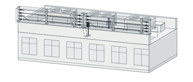
Data centers, corporate headquarters, and embassies often overlook podium rooftops and adjacent building bridges—where intruders cross upper parapets while structural waterproof membranes rule out heavy tensioned anchor posts. EF-350 mounts lightweight array brackets along rooftop parapets and stepped upper walls, dividing up to 2 × 150 m (Zone A and Zone B) per processor into crisp alarm segments. Its narrow ≤0.5 m field hugs the parapet edge so rooftop HVAC servicing inside the roof deck proceeds undisturbed.

Plan this perimeter →
Podium rooftop parapet layout
Rooftop Parapet Edge Array
Rooftop parapet edge array
Zone A (up to 150 m) + Zone B (up to 150 m)
≤0.5 m edge-aligned field
Interior rooftop HVAC service walkway
04 — Field deployment

Engineered for the boundary you operate.

Scenario 05 · Terrain-Following Compounds and Fail-Safe I/O

Follow Rolling Compound Grades and Integrate via Fail-Safe Relays or RS-422

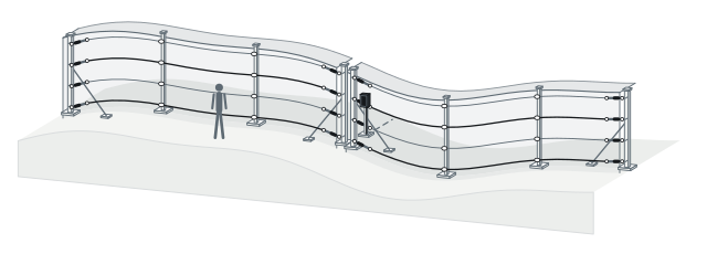
Sloped depot perimeters force straight infrared or microwave beams into short, costly segments to prevent crawl-under gaps in ground dips. EF-350 carries freestanding or fence-mounted parallel wires smoothly across rolling elevation changes while maintaining consistent field height from bottom wire to top wire. Each 400 × 235 × 165 mm processor (optional 984 × 425 × 273 mm cabinet) delivers 4 fail-safe Form C relays (1.0 A, 30 VDC, 0.125–10 s), 2 self-test/dry-contact inputs, and optional RS-422 plus +8 relay / +8 input expansion.

Plan this perimeter →
Terrain-following freestanding/fence array
Zone A Terrain-Following Array
Zone A terrain-following array
Up to 150 m
Zone B terrain-following array
Up to 150 m
Processor · 400 × 235 × 165 mm
Optional 984 × 425 × 273 mm cabinet
4 fail-safe relays (0.125–10 s) + 2 inputs + optional RS-422 / +8 I/O
05 — System architecture and bill of subsystems

Wire Arrays on the Perimeter, <6 W IP66 Processing at the Zone Split

An EF-350 installation pairs unpowered outdoor support brackets and parallel field/sense wire arrays with a single <6 W IP66 processor positioned between Zone A and Zone B—connecting cleanly to standalone relay panels or networked RS-422 head-ends.
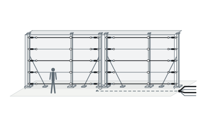
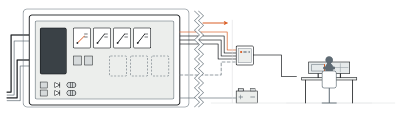
FIELD ASSEMBLY≤0.5 m · non-shockingZone A + Zone B · 2 × 150 m
Zone A Parallel Field + Sense Wires
01
Zone A parallel field + sense wires
Up to 150 m
02
Zone B parallel field + sense wires
Up to 150 m
PROCESSING / CONTROL12–48 VDC · <6 WAlarm dispatch + camera cue
EF-350 IP66 Processor · 12–48 VDC · <6 W
03
EF-350 IP66 processor · 12–48 VDC · <6 W
-40°C to +70°C
04
Onboard 4 fail-safe Form C relays (1.0 A, 30 VDC) + 2 supervised inputs
05
Optional RS-422 (A/B Tx/Rx) + 8-relay card + 8-input card
06
Security control room / VMS camera presets

System components and trade interfaces

Subsystem Layer
Components Included
Power Status
Location and Trade Scope
01 · Parallel Field and Sense Wire Arrays
4-wire (2.45 m) or 5-wire (3.65 m) basic zone arrays, stackable to 9 wires (6.8 m) or 10 wires (7.3 m) on fences, with insulated standoffs and terminations
Low-frequency electrostatic excitation from EF-350 processor (non-shocking)
Freestanding, fence-mounted, wall-top (≤6.1 m), or rooftop line · Perimeter bracket installation
02 · EF-350 Dual-Zone IP66 Processor
IP66 outdoor processor (400 × 235 × 165 mm) driving Zone A and Zone B (up to 150 m each), with gas-discharge surge protection and optional 984 × 425 × 273 mm cabinet
Powered (12–48 VDC main input, <6 W; auxiliary rating 18–52 VDC in / 12 VDC, 150 mA out)
Boundary zone split post or protective telecom cabinet · SI mounting and termination
03 · Onboard Fail-Safe Relays and Inputs
4 programmable Form C relays (1.0 A, 30 VDC, 0.125–10 s, fail-safe) + 2 supervised inputs (standalone self-test or networked dry-contact mode)
Powered internally by EF-350 processor
Inside IP66 processor enclosure · Direct hardwired tie-in to alarm panel / NVR
04 · Optional Network and I/O Expansion
Optional RS-422 / EIA-422 network card (A and B side Tx/Rx), +8 Form C relay card (1.0 A, 30 VDC), and +8 configurable supervised dry-contact input card
Powered internally by EF-350 processor; head-end on control-room UPS
Multi-processor perimeter bus to security control room · SI commissioning
06 — Technical specifications

PerimField EF-350 Full Engineering Specifications

Detection Performance
Parameter
Standard Specification
Sensing Principle
Non-shocking low-frequency electrostatic volumetric field around parallel field and sense wires
Zones and Maximum Length
2 zones per processor (Zone A and Zone B); up to 150 m per zone
Detection Probability (Pd)
95% for an upright ≥35 kg person crossing the detection zone at 5 cm/s to 8 m/s
Walk-Up Detection Width
Up to 0.5 m maximum width for an upright ≥35 kg person (tall, narrow contained profile)
Detected Intrusions
Human approach or wire penetration, plus tall metal objects disturbing the electrostatic field
Grid Immunity and Filtering
Immune to 50 Hz and 60 Hz power-grid interference; enhanced DSP environmental stimulus filtering
Electrical and Surge
Parameter
Standard Specification
Main Input Supply and Power
12–48 VDC main input; power consumption <6 W
Auxiliary Supply Specification
18–52 VDC input; 12 VDC, 150 mA output
I/O Port Surge Protection
Transient suppression diodes and non-isotope gas discharge devices on all I/O ports
Wire Array Geometry
Parameter
Standard Specification
Basic Zone Wire Layouts
4-wire or 5-wire parallel arrays per zone; stackable configurations supported
Fence-Mounted Maximum Heights
4 wires: 2.45 m; 5 wires: 3.65 m; 9 wires: 6.8 m; 10 wires: 7.3 m
Freestanding and Wall-Top Height
Up to 6.1 m maximum detection zone height
Mounting Modes and Terrain
Freestanding, fence-mounted, wall-top, and rooftop installations; terrain-following supported
Onboard and Optional I/O
Parameter
Standard Specification
Onboard Relay Outputs
4 Form C relays rated 1.0 A at 30 VDC; assignable functions; programmable 0.125–10 s fail-safe output
Supervised Auxiliary Inputs
2 inputs (self-test inputs in standalone mode; configurable supervised dry-contact inputs in network mode)
Optional Network Card
RS-422 / EIA-422 network card with A and B side Tx/Rx connections
Optional I/O Expansion Cards
8-channel Form C relay card (1.0 A, 30 VDC); 8-channel dry-contact input card with configurable thresholds and supervision
Mechanical and Environment
Processor and Cabinet Dimensions
Processor: 400 × 235 × 165 mm (H × W × D); optional protective telecom cabinet: 984 × 425 × 273 mm
Enclosure and Operating Climate
IP66 enclosure; -40°C to +70°C operating temperature; 0–95% RH (non-condensing)

Above values reflect standard product technical specifications. Stacked 9-wire (6.8 m) and 10-wire (7.3 m) zone allocation, bracket spacing, and RS-422 bus topology are matched to your project drawings during design.

07 — Engineering FAQ

Common Questions Before Specifying EF-350

01Is EF-350 a high-voltage electric shock fence?

No. EF-350 is a non-shocking, non-lethal low-frequency electrostatic volumetric space sensor (<6 W processor draw). Instead of delivering high-voltage shocks upon wire contact, it senses capacitive field changes within ≤0.5 m when an intruder or tall metal ladder approaches or crosses the parallel wire array—making it suitable beside public walkways and staff patrol lanes.

02When should we specify EF-350 electrostatic arrays versus PerimTaut TW-100 taut-wire fencing?

Specify EF-350 when you want early approach-and-crossing space sensing before physical contact, lightweight rooftop/parapet brackets, or stacked vertical fence coverage up to 7.3 m across 2 × 150 m processor zones. Specify PerimTaut TW-100 when your perimeter requires a 0 W purely mechanical barbed-wire physical barrier that resists climbing and cutting without any outdoor electronics.

03How do 4-wire, 5-wire, and stacked 7.3 m configurations relate to the 2 × 150 m processor capacity?

In standard 4-wire (2.45 m) or 5-wire (3.65 m) layouts, 1 EF-350 processor monitors 2 independent zones (Zone A and Zone B) of up to 150 m each. When stacking dual arrays vertically on a high-security fence to reach 6.8 m (9 wires) or 7.3 m (10 wires), our engineering team maps the A/B channel pairing to match your exact fence height and zone length.

04How are vehicle gates and open road crossings protected along an EF-350 boundary?

EF-350 wire arrays terminate cleanly on insulated end posts flanking each gate opening. Across the movable vehicle gate span itself, engineers typically pair a fixed bistatic microwave link such as PerimWave MW-400 (5–200 m) or conceal PerimTerra BF-300 buried RF cables beneath the paved roadway, tying all zone alarms into the same head-end.

08 — Next step

Get a Preliminary EF-350 Wire-Array Layout and Equipment Supply Quote

Send us your boundary dimensions, mounting structure photos or drawings, and nearby clearance widths. Our engineering team will configure 4/5/9/10-wire array heights, place <6 W IP66 processors, and prepare an equipment supply quotation.

01Total boundary length, elevation changes, and desired zone split (up to 150 m per zone)
02Mounting surface: freestanding ground, high-security fence (up to 7.3 m), wall top (up to 6.1 m), or rooftop parapet
03Clearance to nearby patrol lanes, sidewalks, or 50/60 Hz high-voltage power infrastructure
04Control-room integration preference: 4 onboard fail-safe relays, +8 I/O expansion, or RS-422 networking
Substations ↗Data Centers ↗Private Estates ↗Oil and Gas Terminals ↗Solar and Battery Storage ↗How PIDS Works ↗Power Planning Guide ↗Installation and Maintenance ↗Compare All Products ↗