Engineering Guide · Power, Wiring, and Fault Architecture
Passive Sensing, System Power, and Wiring Architecture for Perimeter Intrusion Detection
In perimeter intrusion detection, passive outdoor sensing elements operate at 0 W without field power. Powered collection modules, optical processors, network switches, cameras and operator panels turn their signals into verified alarms. Use the topologies and worksheets below to map power drops, cable budgets, UPS coverage and recovery paths before civil trenching starts.
- Core Rule
- 0 W passive barrier wires/switches and optical fibers connect to powered processing and communications equipment
- Four Standard Topologies
- Mechanical near-sector (A1), mechanical centralized (A2), passive optical (B), and active field (C)
- Engineering Worksheets
- L1–L2 cable schedule, node load and UPS sheet (P = V × I), line budget, and F1–F6 fault matrix
- Initial Deliverable
- Preliminary zone and power-location proposal plus equipment supply quote
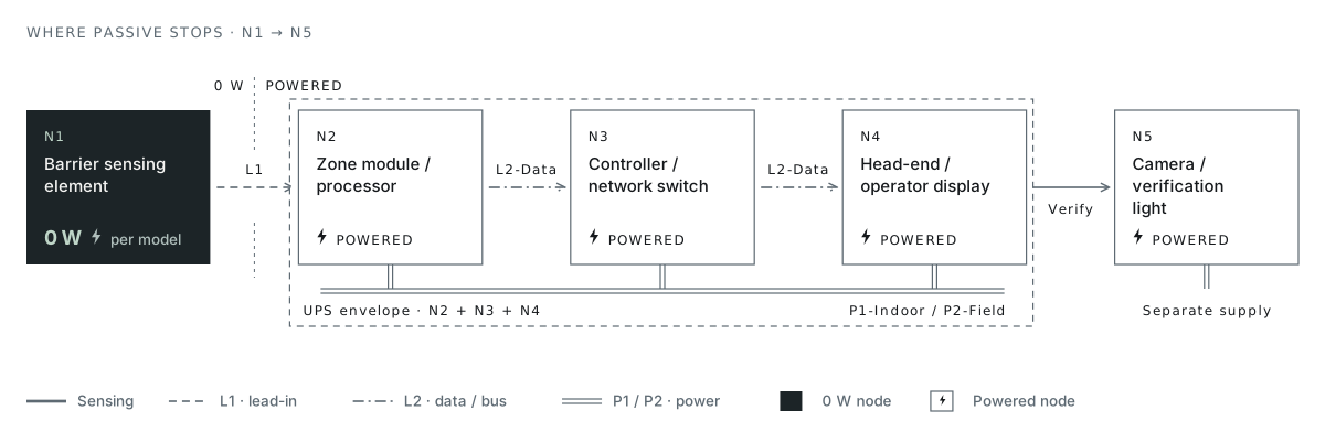
N1 · Barrier Sensing Element (0 W on TW/FF/FO; Powered on Active Models)
N2 · Zone Module or Sensor Processor (Always Powered)
N3 · Alarm Controller and Network Switch (Always Powered)
N4 · Control-Room Head-End and Operator Display (Powered)
N5 · Verification Cameras and Lighting (Powered Separately)
Mechanical L1-Mech is governed by loop impedance and input specifications. P1-Indoor and P2-Field feed the nodes in the selected configuration.
01 — Mechanical passive topologies (A1 and A2)
Place PerimTaut Backend Collection Near the Sector (A1) or Centrally (A2)
On PerimTaut TW-100 and TW-150 barriers, tensioned wires and post-mounted mechanical switches operate at 0 W and are unaffected by electromagnetic and radio-frequency interference (EMI/RFI), while on-site adjustable pull thresholds filter out animal and plant contact. Where the powered alarm interface sits depends on perimeter geometry and verified cable limits:
01
Topology A1 · Sector-Near Protected Enclosure Collection
Short dry-contact signal cables (L1-Mech) run from 0 W detector posts to a powered collection cabinet located in a nearby substation bay house, gatehouse, or weatherproof roadside enclosure (fed by P2/UPS power), which then transmits alarms over network/bus link L2 to the central control room.
02
Topology A2 · Equipment-Room Centralized Collection
On compact sites where total metallic cable distance and loop resistance from each detector post to the building stay within the selected interface's allowed range, dry-contact runs (L1-Mech) home-run directly into powered modules/controllers inside the central equipment room (P1/UPS)—eliminating outdoor power enclosures altogether.
03
Backend Configuration Options
PerimTaut supports a 24 VDC two-zone alarm module (12 DI / 6 DO, dry/wet contact) and a 9–24 VDC alarm controller (8+ switch outputs, network/relay reporting). Select backend hardware for the project and plan contact logic, line supervision and L1-Mech distance using the selected module and controller data.
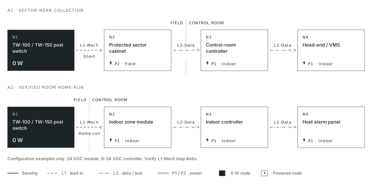
N1 · TW-100 / TW-150 post switch [0 W] — L1-Mech → N2 · Protected sector cabinet [⚡ P2] — L2-Data → N3 · Control-room controller [⚡ P1] — L2-Data → N4 · Head-end / VMS [⚡ P1]
N1 · TW-100 / TW-150 post switch [0 W] — L1-Mech → N2 · Indoor zone module [⚡ P1] — L2-Data → N3 · Indoor controller [⚡ P1] — L2-Data → N4 · Host alarm panel [⚡ P1]
Mechanical L1-Mech is governed by loop impedance and input specifications. P1-Indoor and P2-Field feed the nodes in the selected configuration.
02 — Passive optical (B) and active field (C) topologies
Contrast Optical Lead-In Architectures (B) Against Powered Field Devices (C)
Compare the remaining two PerimSense power families using the same N1–N4 nodes and L1/L2/P1/P2 links. Calculate optical sensing paths and metallic contact loops with their respective design criteria:
01
Topology B · Passive Optical Sensing + Non-Sensing Lead-In (FF-200, FF-250, FO-700, FO-750)
:
- The barrier fiber itself operates at 0 W with zero field electronics. Non-sensing optical lead-in cable (L1-Opt) bridges the passive boundary to a powered demodulator/processor (N2, fed by P1)—for example, up to 20 km of single-mode non-sensing lead-in fiber to a 12–48 VDC or PoE (2 W nominal) processor on FO-750, up to 80 km fence / 100 km buried sensing reach per indoor processor on FO-700, and 12–30 VDC (65 mA max) zone processors on FF-200 and FF-250.
- Separate Engineering Budgets: Calculate optical path loss from splices, connectors, and fiber attenuation; calculate indoor processor electrical supply separately. Design TW dry-contact loops to their electrical interface specifications.
02
Topology C · Powered Field Perimeter Security Devices (BF-300, PM-280, EF-350, MW-400, MW-450M, VC-600, LP-500)
:
- Field processors, transceivers, bus modules, or luminaires require electrical supply at or along the perimeter (P2): 12–48 VDC processors on BF-300 (<9 W), EF-350 (<6 W), and MW-400 (1.5 W Tx / 2.6 W Rx); 10–60 VDC (2.0–2.5 W) or optional PoE processor on VC-600 (cable power per configuration); powered local controller feeding ≤2 W 1-to-4 DC bus modules on PM-280; 12–48 VDC fence-line bus (2.5 W/luminaire) plus gateway on LP-500; and swappable 12 V lithium battery packs (nominal 30 h standby depending on temperature and mode) on portable MW-450M.
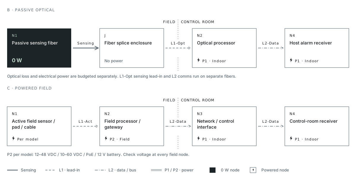
N1 · Passive sensing fiber [0 W] — Sensing → J · Fiber splice enclosure [No power] — L1-Opt → N2 · Optical processor [⚡ P1] — L2-Data → N4 · Host alarm receiver [⚡ P1]
N1 · Active field sensor / pad / cable [⚡ per model] — L1-Act → N2 · Field processor / gateway [⚡ P2] — L2-Data → N3 · Network / control interface [⚡ P1] — L2-Data → N4 · Control-room receiver [⚡ P1]
Mechanical L1-Mech is governed by loop impedance and input specifications. P1-Indoor and P2-Field feed the nodes in the selected configuration.
03 — Cable and interface schedule
Match Every Link Code (L1–L2, P1–P2) on Your Site Drawing
Every line on Figures 24.1–24.3 maps to a specific link row below. Use this architecture schedule to align civil conduits and cable types before ordering—remembering that terminal pinouts come from the approved wiring diagram for your exact model version.
Scroll across for all fields; mobile shows labeled records.
| Link ID | From → To Nodes | Link Purpose | Medium and Interface Options | Documented Allowance or Constraint | Termination, Surge, and Supervision | Basis and Project Items to Confirm |
|---|---|---|---|---|---|---|
| L1-Mech | N1 (TW-100/TW-150 post switch) → N2 (zone module / controller) | Intrusion, tamper, and optional anti-cut contact sensing loop | Multi-core copper control cable; dry/wet contact input per module | Governed by metallic loop resistance, cable capacitance, and module input specifications | Weatherproof post gland; surge protection at powered N2 entry; EOL supervision confirmed per module | PerimTaut configuration datasheet; confirm A1 vs A2 run length and conduit route |
| L1-Opt | N1 (FF/FO passive fiber) → N2 (optical processor) | Optical sensing return / non-sensing optical lead-in | Single-mode / armored optical cable per model (FO-750 lead-in up to 20 km; FO-700 up to 80 km fence / 100 km buried) | Optical dB loss budget across fiber length, fusion splices, and clean optical connectors | Dedicated splice enclosure; minimum bend radius; zero electrical surge conduction on all-dielectric fiber | FF-200, FF-250, FO-700, FO-750 specs; confirm splice count and duct path |
| L1-Act | N1 (active cable/pad/luminaire) ↔ N2 (field processor/controller) | Active RF coax (BF-300), DC/RS-485 bus (PM-280), field wire (EF-350), or vibration coax (VC-600) | Dedicated sensor coax (800 m max/processor on BF-300; 600 m on VC-600), 2 × 150 m array (EF-350), 1-to-4 bus (PM-280) | Use the specified sensor cable with the model-specific length and characteristic impedance | Factory-specified connectors/terminators and processor-end grounding/surge arresters | Respective active model manual; confirm VC-600 cable power mode and PM-280 bus voltage |
| L2-Data | N2/N3 (module/processor/gateway) → N4 (host security panel / VMS) | Alarm, fault/tamper, and coordinate/zone reporting | Form C relays (30 VDC, 1.0 A on FO-750/VC-600/BF-300/EF-350/MW-400/MW-450M), RS-422 (1.2 km option), Ethernet/PoE, or MM (2.2 km) / SM (10 km) comm fiber cards where offered | Copper Ethernet ≤100 m per hop; RS-422 / optical comm card distances per selected plug-in card | Surge protection on outdoor copper serial/Ethernet; distinct from L1-Opt sensing fiber! | Selected processor/controller I/O option card and installed site head-end interface |
| P1-Indoor | Building AC/DC UPS → N2/N3/N4 (indoor rack/cabinet) | Protected indoor equipment power | 12–30 VDC (FF), 12–48 VDC or PoE (FO-750), 9–24 VDC / 24 VDC (TW examples), or AC/DC per FO-700 spec | Voltage regulation and breaker sizing at indoor rack | Site main earthing bar and AC/DC SPD protection | Electrical room schedule and target UPS runtime |
| P2-Field | Perimeter feeder / PoE switch / battery → N2 (A1 cabinet or C field devices) | Distributed outdoor equipment or luminaire bus power | 12–48 VDC (BF-300, EF-350, MW-400, LP-500), 10–60 VDC / PoE (VC-600), 12 V lithium pack (MW-450M) | Conductor gauge sized for ΔV = I_peak × R_loop so far-end voltage stays above model minimum | Outdoor enclosure IP rating, local ground rod/bonding, and DC surge protection | Site electrical feeder length, ambient temperature, and battery swap/UPS plan |
04 — Node load and standby power worksheet
Plan Power and Backup for Every Active Device
01
Single DC Device Power
P = V × I. Use the rated input voltage and operating/peak current of the selected configuration to calculate its load. Size the power supply for the combined connected loads.
02
DC Feeder Voltage Drop
ΔV = I_peak × R_loop (Verify V_supply_min − ΔV ≥ V_device_min at the farthest node under peak current, including cold-start or alarm-relay/strobe surge.)
03
Standby Battery Planning
Separate Essential Detection and Reporting Loads (zone modules, processors, controllers, fiber switches) from High-Draw Companion Loads (perimeter floodlights, PTZ heaters). The project electrical engineer selects battery capacity (Ah) from confirmed active loads, required autonomy hours, DC/AC conversion efficiency, usable depth-of-discharge, and temperature/aging derating. Mark pending load values Unknown and complete them during project design; record 0 W field sensors separately from powered backend equipment.
Scroll across for all fields; mobile shows labeled records.
| Node ID | Component / Model / Configuration | Location | Qty | Input Supply Range | Nominal Draw | Peak / Strobe / Startup Draw | Temp and Accessory Notes | Target Backup Hours | Assigned Supply / UPS | Source Basis | Review Status |
|---|---|---|---|---|---|---|---|---|---|---|---|
| N1-TW | TW-100 / TW-150 mechanical post switch | Barrier post | [Qty] | None (0 W) | 0 W | 0 W | -40°C to +72°C mechanical | N/A (Passive) | None | Current manual | Confirmed 0 W |
| N2-TW | TW 24 VDC 2-zone module / 9–24 VDC controller (config examples) | A1 cabinet or A2 room | [Qty] | 24 VDC / 9–24 VDC (per config) | Unknown (confirm per selected unit) | Unknown (confirm relay/comm peak) | Check cabinet temp and comm card | [e.g., 4 h / 24 h] | [P1 or P2 UPS] | Config datasheet | Confirm at order |
| N2-FF | FF-200 / FF-250 IP66 zone processor | Near fence / culvert or room | [Qty] | 12–30 VDC | ≤65 mA (~0.8–2.0 W) | Confirm relay state | Passive fiber at fence/grille (0 W) | [Fill hours] | [P1 / P2 UPS] | Product spec | Nominal known |
| N2-FO750 | FO-750 4-zone optical processor | Indoor rack / DIN rail | [Qty] | 12–48 VDC or PoE | 2 W nominal | Confirm PoE class | Up to 20 km passive lead-in | [Fill hours] | [P1 / PoE UPS] | Product spec | Nominal known |
| N2-FO700 | FO-700 long-range optical processor | Indoor telecom / control room | [Qty] | Unknown (per selected processor spec) | Unknown (per selected spec) | Unknown (per selected spec) | Field fiber 0 W up to 80/100 km | [Fill hours] | [P1 Room UPS] | Selected spec | Confirm at order |
| N2-Act | Active processor (BF-300 <9 W · EF-350 <6 W · MW-400 1.5+2.6 W · VC-600 2.0–2.5 W · PM-280 ≤2 W/mod + ctrl) | Perimeter enclosure | [Qty] | 12–48 VDC (10–60 VDC / PoE on VC-600) | Model nominal | Confirm cold-start / comm card | MW-450M uses 12 V battery (30 h nom., temp-dependent) | [Fill hours] | [P2 Feeder / Battery] | Product specs | Check run ΔV |
| N5-LP | LP-500 fence luminaire + mesh gateway | Fence posts + gateway point | [Qty] | 12–48 VDC (PoE opt. on gateway) | 2.5 W / light; 0.5–1.0 W gateway | Check full-bright / strobe bus current | Separate lighting bus from core alarm UPS if needed | [Fill hours] | [Lighting DC / UPS] | Product spec | Size bus gauge |
| N3/N4/N5-Site | Site Ethernet switches, media converters, CCTV cameras, and VMS/panel | Field cabinets and control room | [Qty] | [Site Spec] | Unknown (by SI / Owner) | Unknown (IR LEDs / PTZ heaters) | Back up N3/N4 to keep the alarm path available | [Fill hours] | [Site UPS] | SI / Owner BOM | Mandatory SI input |
05 — Line budget and environmental exposure
Verify Copper Voltage Drop, Contact Loop Limits, and Optical Loss with Separate Rules
Apply the appropriate electrical or optical design criteria to each link: DC power feeders, dry-contact switch loops, RS-422/Ethernet data, and single-mode optical fiber.
| Link Constraint Category | Required Site Inputs | Verification Basis | Result Action if Margin Is Tight |
|---|---|---|---|
| 01 · Low-voltage DC feeder drop (P2-Field) | Supply voltage, one-way run length, conductor cross-section (mm²/AWG), ambient wire temperature, and summed I_peak | Calculate ΔV = I_peak × R_loop; verify farthest processor or last LP-500 luminaire receives ≥12 VDC (or ≥10 VDC on VC-600) | Step up conductor gauge, raise source tap within rated 12–48 VDC window, or split into shorter local power drops |
| 02 · Metallic dry-contact / bus loop (L1-Mech / PM-280) | Run length from post/pad to module, cable gauge/shielding, parallel HV exposure, and EOL resistor supervision requirement | Check the selected module/controller maximum loop resistance and capacitance | Switch from centralized A2 to sector-near A1 enclosure collection and carry long haul over fiber L2-Data |
| 03 · Optical sensing and lead-in loss (L1-Opt) | Sensing + lead-in fiber km, fusion splice count, bulkhead connector count, and fiber attenuation (dB/km) | Verify total optical link loss stays within the selected FF or FO processor optical budget | Minimize mechanical connectors via fusion splicing, clean ferrules before commissioning, and verify OTDR/power-meter trace |
| 04 · Outdoor conduits, earthing, and surge (All Metallic Links) | Lightning flash density, soil resistivity, water-table flooding in pits, and coastal/UV exposure | Bond outdoor metallic enclosures and surge arresters to site earthing rules; seal conduits against water/rodents | Replace long inter-building copper data runs (L2-Data) with dielectric single-mode/multimode optical fiber links |
06 — Failure impact and recovery matrix
Trace Exactly What Survives—and What Goes Blind—Under Six Failure Modes
Map UPS coverage to the nodes it supplies, then verify detection, video and reporting through six breakpoint scenarios (F1–F6). Record fault visibility and recovery steps for each link.
| Breakpoint ID and Fault Scenario | What Still Senses at the Boundary | What Still Reaches the Operator | Visible Fault or Tamper Indication (Where Supported) | Post-Recovery Verification Step | Responsible Role |
|---|---|---|---|---|---|
| F1 · Sector collector / processor power loss (N2 dark) | 0 W TW post switches still actuate mechanically and optical fibers remain intact, but N2 cannot read or demodulate them; active C sensors stop sensing | Affected sector stops reporting intrusion alarms; unaffected UPS-backed sectors continue | Power-loss / heartbeat fault at central controller or VMS (where supervised link/input is configured) | Confirm N2 auto-restart, clear latched faults, and perform walk-test on affected sector | SI / Facilities Electrical |
| F2 · Main site AC outage (P1/P2 on vs off UPS) | All nodes wired to sized UPS/battery packs (MW-450M internal pack) continue normal sensing | End-to-end reporting continues only if N2, N3 network switches, and N4 head-end are all on backup power | AC-fail / on-battery status reported by UPS or power supply supervisory relay | Verify battery recharge state and check event logs for any gap if autonomy was exceeded | Owner Facilities / Security |
| F3 · Tensioned barrier wire cut vs L1 lead-in cable fault | Cutting a TW barrier wire triggers the N1 post switch; severing/shorting L1-Mech or L1-Opt interrupts the path behind N1 | TW wire cut reports zone intrusion alarm; L1-Opt fiber break reports optical fault/alarm at processor; L1-Mech open/short behavior depends on dry-contact / EOL supervision wiring | Optical loss alarm (FF/FO) or supervised loop fault/tamper (TW/relay inputs where configured) | Repair/re-tension wire or re-splice cable, then run full start/mid/end zone pull and fault tests | Fence/Cable Crew + SI |
| F4 · Field-to-room network / comm link drop (L2 broken) | N1 and powered N2 continue local sensing and relay switching (local LP-500 strobe still triggers) | Live alarms do not reach N4 during outage; models with documented local buffering (FO-750, LP-500 gateway) queue events for reconnection | Comm-loss / polling timeout alarm on N4 head-end VMS or panel | Confirm link restoration, verify queued event upload (where supported), and test live alarm | SI / IT Network Team |
| F5 · Head-end VMS / workstation offline (N4 down) | N1, N2, and N3 remain fully operational | Operator screen is dark unless secondary hardwired annunciator or redundant server exists | Watchdog / secondary panel alert per site control-room design | Restore head-end service and reconcile controller logs against downtime window | Owner Security / IT |
| F6 · Verification camera or fence lighting outage (N5 down) | Perimeter intrusion detection (N1–N4) remains 100% active | Operator receives zone/location intrusion alarm normally, but lacks live visual confirmation | Camera video-loss or lighting circuit breaker fault on site VMS/BMS | Dispatch mobile patrol for physical verification until camera or lighting circuit is restored | Security Patrol / Facilities |
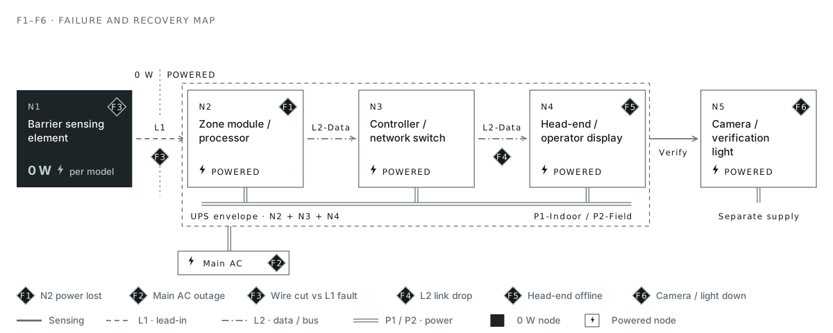
Must include N2 (Module/Processor) + N3 (Switch/Converter) + N4 (Alarm Receiver).
F1 at N2 power · F2 at Main AC · F3 on N1 wire vs L1 cable · F4 on L2 comm link · F5 at N4 workstation · F6 at N5 camera/light.
Mechanical L1-Mech is governed by loop impedance and input specifications. P1-Indoor and P2-Field feed the nodes in the selected configuration.
07 — Project power brief
Share Your Power Locations and Route Distances for Configuration Review
Bring whatever power and routing notes you already have—even with Unknown cells left open. Our team will map candidate PerimSense models, confirm interface options, and provide a preliminary zone proposal and equipment supply quote.
Tier 1 · Send Now to Start
- Candidate sensor family or boundary task (passive taut-wire TW-100/TW-150, passive fiber FF/FO, or active field models)
- Available power locations (central control room only, gatehouses/substation bays, or perimeter DC feeders)
- Approximate perimeter zone lengths and distance from the boundary to the nearest equipment room
- Target standby runtime during a mains outage (e.g., core alarm path vs cameras/lighting)
Tier 2 · Checked Together During Detailed Review
- Filled or partial Node Load Worksheet and L1–L2 Cable Schedule rows
- Existing host security panel, VMS, or relay/network interface details
- Site earthing, surge-protection, conduit, or hazardous-area classification drawings
- Related Guide Links: Compare taut-wire mechanisms: Taut-Wire Detection Guide · Prepare field tests and upkeep: Installation, Commissioning, and Maintenance Guide →