Engineering Guide · Land-Based Taut-Wire PIDS
Taut-Wire Detection: Compare Mechanisms and Specify the System
A land-based taut-wire barrier combines physical intrusion delay with pull-and-cut detection in a single tensioned structure—distinct from marine vessel dynamic-positioning taut-wire gear. Use this engineering guide to see how mechanical post switches, electronic strain-gauge systems, and fence-attached optical or microphonic cables actually process force, and carry away a specification worksheet for same-scope project review.
| Project Priority | Why Evaluate PerimTaut Mechanical Taut-Wire First | When to Check Strain-Gauge or Attached-Cable Routes More Closely |
|---|---|---|
| 01 · Physical delay + pull/cut alarm | Builds or tops a barrier where climbing, spreading, or cutting tensioned wires triggers a 0 W mechanical post switch directly—see the PerimTaut TW-100 passive taut-wire fence system and TW-150. | Existing chain-link or architectural fencing must be retained without new tension-anchor footings → evaluate attached passive fiber (FO-750 / FO-700) or modular FF-200. |
| 02 · High electromagnetic exposure + nuisance control | Mechanical post detectors contain zero electronics—unaffected by electromagnetic and radio-frequency interference (EMI/RFI)—while an on-site adjustable pull threshold filters out animal and plant contact alongside slow thermal drift compensation. | Sites requiring multi-kilometer meter-level coordinate cueing along an existing fence (±4 m on FO-700, 3 m on VC-600) rather than discrete physical barrier zones. |
| 03 · Low core upkeep + clear tender scope | Material-based core sensing structure rarely suffers damage while its protective materials remain intact; backend power sits at designated modules/controllers with competitive same-tier pricing and fast factory dispatch. | Tender specifications mandating continuous analog tension telemetry per wire, specific software diagnostic logs, or host protocols that must be verified per vendor document version (#s06). |
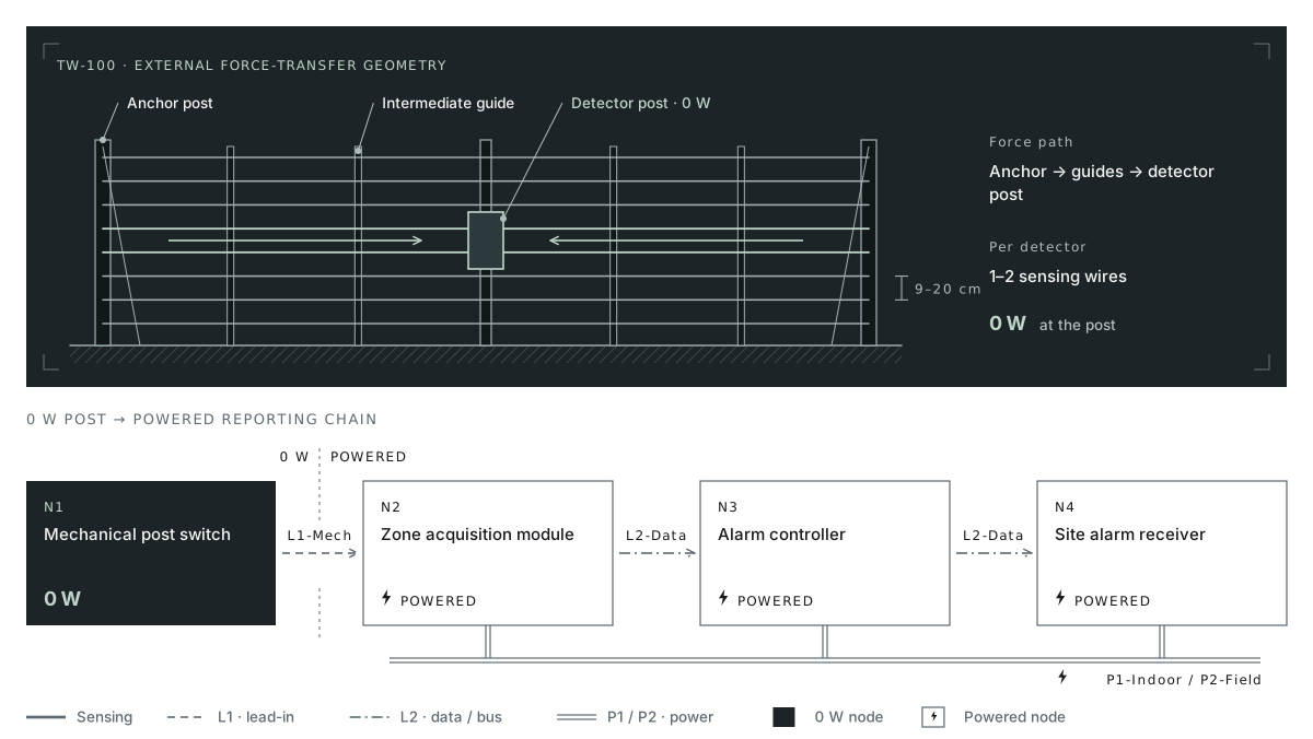
End Anchor Post (Carries Static Wire Tension)
Intermediate Support Post (Guides Wire Spacing)
Center / End Detector Post (0 W Mechanical Switch — Unaffected by EMI/RFI)
Signal Lead-In → Powered Zone Module and Alarm Controller (Per Configuration)
01 — System anatomy and force transfer
Map External Components and Force Paths on TW-100 vs TW-150
Civil contractors, fence erectors, and security integrators coordinate the structure, barrier, and alarm interfaces of a taut-wire zone. Plan TW-100 parallel-wire fencing and TW-150 concertina razor coils around their respective mechanical load paths.
PerimTaut TW-100
Parallel Tensioned Wire Barrier (03-tw100.html)
External Structure
Heavy-duty end/corner anchor posts hold parallel stainless wires (9–20 cm vertical spacing) under tension across intermediate support posts that guide alignment without clamping axial movement. Each mechanical post detector terminates 1–2 sensing wires.
Interface Split
Civil/fence scope covers concrete footings or wall-coping bolts, corner bracing, gate terminations, and wire tensioning; SI scope covers dry-contact zone/tamper wiring from detector posts to powered backend equipment.
PerimTaut TW-150
Tension-Sensing Concertina Razor Coil (04-tw150.html)
External Structure
Mounted along rigid wall copings, verified structural fence tops, or controlled high-security ground corridors. Per the current PerimSense product specification, each unpowered mechanical detector connects to 1 internal tensioned sensing wire running through the concertina coil assembly (with an optional built-in anti-cut monitored coil loop).
Integrated Force Transfer
Pulling, spreading, or cutting the coil transfers axial load to the sensing wire and detector post. Design TW-150 as an integrated barrier system with rigid supports and matched coil connections.
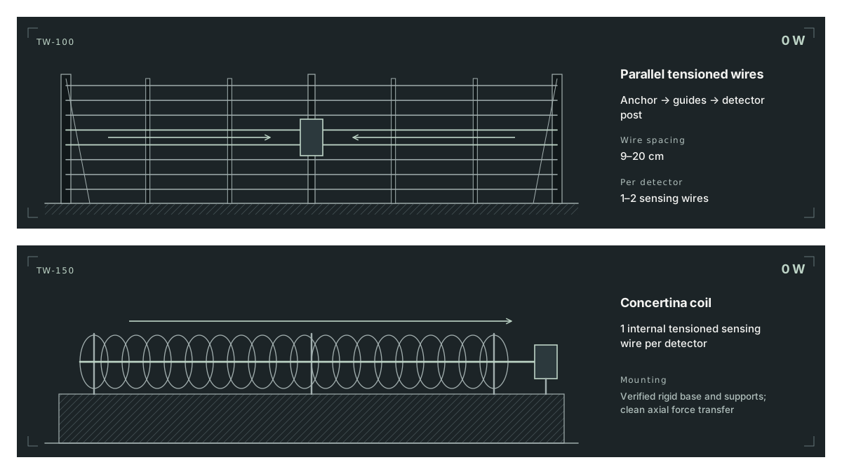
Anchor Post (Fixed End) ↔ Guided Parallel Wires (9–20 cm, Axial Force Vector →) ↔ Detector Post (1–2 Wires per 0 W Switch) → Zone Signal Cable.
Verified Rigid Coping / Rail + Support Brackets ↔ Concertina Coil Tied to 1 Internal Tensioned Sensing Wire (Force Vector →) ↔ 0 W Detector Post.
02 — Three functional states
Trace Signal Changes Across Rest, Intrusion Pull, and Wire Cutting
Pulling a wire and cutting a wire are opposite mechanical events—one spikes tension above the rest window, while the other collapses tension completely. Both actuate the post switch without field power.
01
State 01 · Normal Tensioned Equilibrium (Closed / Normal Loop)
Wires or sensing coil wire hold static installation tension between anchor and detector posts. Animal and plant contact below the on-site pull threshold leaves the mechanical switch in its normal resting contact state.
02
State 02 · Deliberate Pull, Climb, or Wire Spreading (Over-Threshold Deflection → Alarm)
Climbing weight or prying apart wires deflects the span and increases axial pull on the detector post beyond the on-site pull threshold—actuating the mechanical contact state change read by the powered backend zone module.
03
State 03 · Wire or Monitored-Coil Severing (Tension Release → Alarm)
Cutting a tensioned TW-100 wire or severing the TW-150 sensing wire (or optional anti-cut monitored coil loop) abruptly drops resting tension—driving the post mechanism to its release alarm contact position.
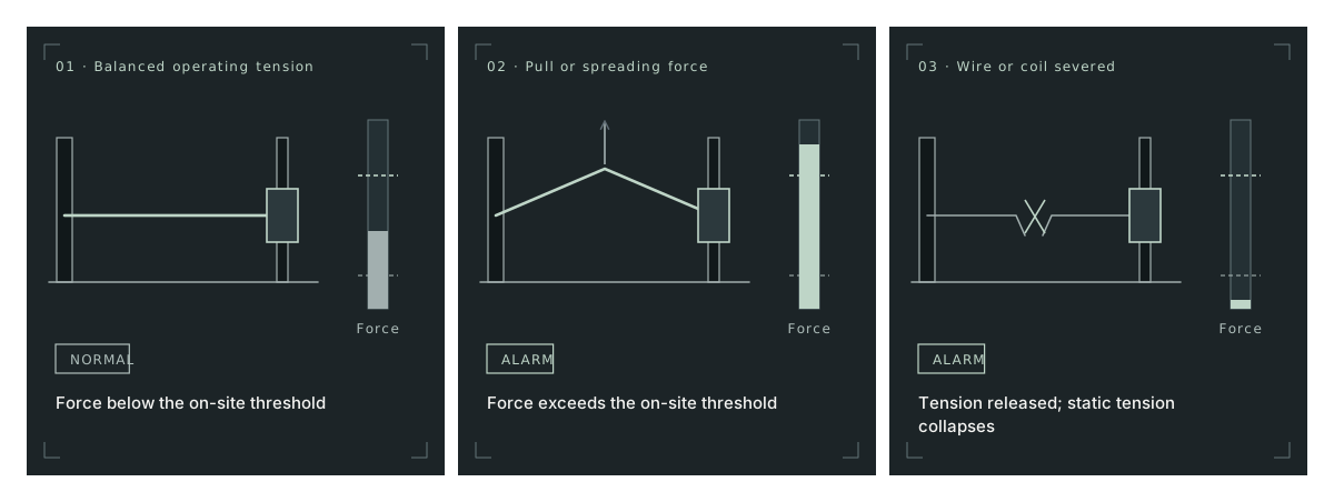
Applied Pull < On-Site Pull Threshold → Tension Balanced → Contact Normal.
Climbing / Spreading Pull > On-Site Pull Threshold → Axial Pull Surge → Contact Opens/Switches to Alarm.
Wire Severed → Static Tension Collapses → Release Contact Switches to Alarm.
03 — Pull threshold vs drift compensation
On-Site Adjustable Pull Thresholds and Automatic Thermal Compensation
Animal and plant contact filtering and seasonal tension stability are two complementary engineering functions. Understanding both helps specifiers and installers define clear commissioning and acceptance criteria.
Function A
On-Site Adjustable Pull Threshold (Filter Out Animal and Plant Contact)
What It Solves
Across PerimTaut TW-100 and TW-150, an on-site adjustable pull threshold filters out animal and plant contact—keeping wildlife and wind-swayed vegetation below the alarm trigger while preserving reliable pull and cut detection.
Commissioning Verification
Set the pull threshold for mechanical load transmitted to the sensing wire and detector post. Pair each adjustment with pull and simulated-cut tests to verify reliable intrusion detection.
Function B
Material-Based Slow Environmental Compensation (Holding Mechanical Equilibrium)
What It Solves
Ambient temperature swings (-40°C to +72°C rated range) and gradual post or soil settlement slowly lengthen or shorten wire spans over hours and seasons. An internal self-adjusting stage accommodates that gradual drift so the resting operating point stays stable without constant seasonal retensioning.
Engineering Practice
Slow-drift compensation stabilizes baseline tension within the installed mechanical range. Plumb posts, sound anchors and pull tests support reliable detection across gradual environmental changes.
See how post-adjustment verification tests are logged on PIDS Installation and Maintenance Guide →
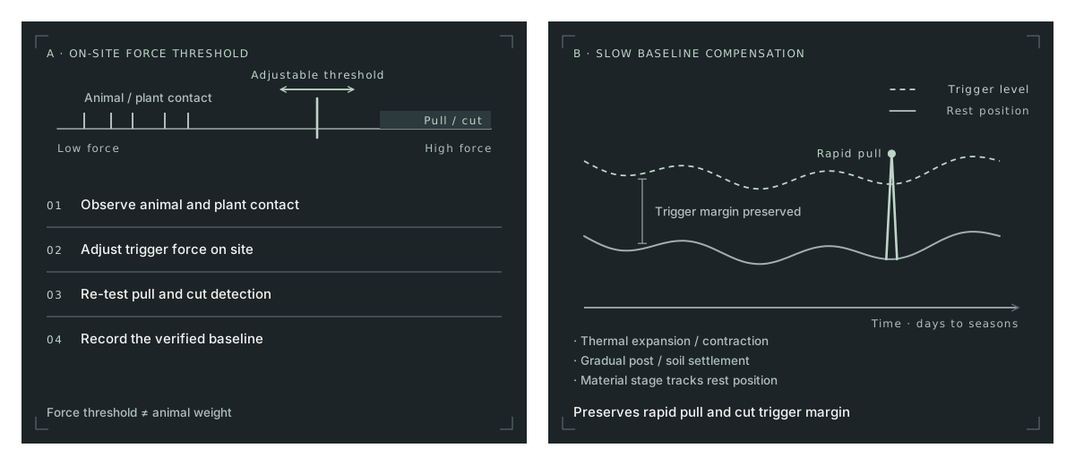
Observe Animal and Plant Contact → Set On-Site Adjustable Pull Threshold → Re-Verify Pull and Cut Detection → Record Baseline.
Thermal Expansion / Contraction + Gradual Post Settlement → Self-Adjusting Material Stage Tracks Rest Position → Trigger Margin Preserved.
04 — Material physics and low upkeep
Understand Why the Core Sensing Structure Rarely Suffers Damage—and What Still Needs Routine Checks
Facility owners rightly ask whether mechanical barriers create heavy ongoing maintenance. On PerimTaut TW-100 and TW-150, the answer separates the sensing core from exposed perimeter hardware and indoor electronics:
01
Material-Property Core Sensing Structure
Detection operates through the physical properties of its materials rather than fragile outdoor circuit boards or optical/electronic transducers. As long as its protective materials remain intact, the core sensing structure rarely suffers damage and requires minimal routine upkeep—with no preset schedule for periodic internal teardown.
02
Three-Layer Maintenance
Keep core detector upkeep minimal, schedule perimeter checks for storm debris, vehicle impacts, vegetation and anchor condition, and include control-room backup batteries in the site maintenance plan.
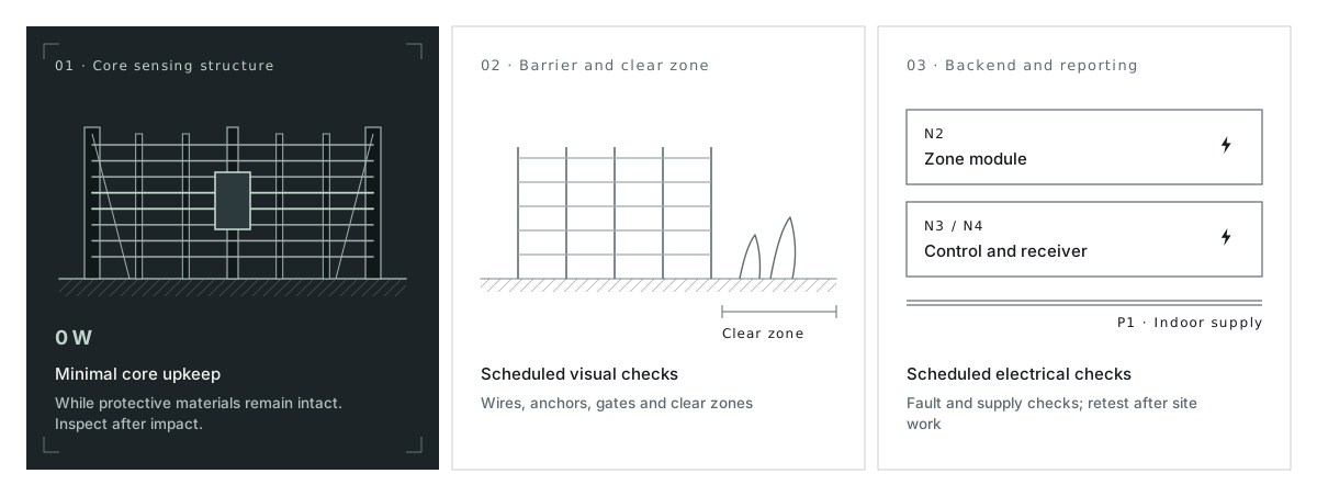
Driven by material physical properties · 0 W post switch · Rarely suffers damage while protective materials remain intact → Minimal routine upkeep; inspect after physical impact.
Tensioned wires / concertina coils, anchor bolts, splices, gates, and vegetation clearance → Scheduled visual and tension walk-checks.
Zone modules, controllers, DC/UPS supplies, surge earthing, and VMS/panel links → Scheduled electrical/fault checks and post-work retesting.
05 — Strain-gauge and attached-cable architectures
Compare Signal Chains by Actual Node Architecture, Not Broad Labels
Compare each architecture by locating its sensing elements, excitation, signal conditioning, reporting interfaces, and power supplies. This gives the project team a clear basis for installation and commissioning:
01
Electronic Strain-Gauge Taut-Wire Signal Chain
Wire tension loads a resistive strain element at the post → an electrically excited bridge and conditioning circuit convert small resistance shifts into voltage/digital readings → compensation algorithms separate slow thermal drift from intrusion events → line/post processors report zone or unit alarms and diagnostic states.
02
Why Configuration Details Matter Across Vendors
Published architectures vary by model and document edition. For example, Magal's publicly accessible DTR brochure pairs self-adjusting mechanical sensors with powered field reporting units (SPRU/GPRU), while DeTekion's 2015-dated VTW-400 brochure (©2013) documents STW-40 strain sensors, FP-450 processing, local computer diagnostics, and optional OMNI remote sensitivity/control capability; multi-version families such as GPS Standard TPS even distinguish mechanical lever/switch (TPSM200) and electronic microphonic (TPSE100) versions. Always check the exact node power, wiring, and diagnostic scope of the offered configuration.
03
Attached Optical Fiber and Vibration Cables (Host-Fence Monitoring)
PerimOptic FO-750 (zoned passive fiber), FO-700 (locating passive fiber), and PerimVibe VC-600 (locating vibration cable) attach to an existing or newly built fence/coil to detect transmitted structural vibration, with powered indoor/enclosure processors and software sensitivity configuration.
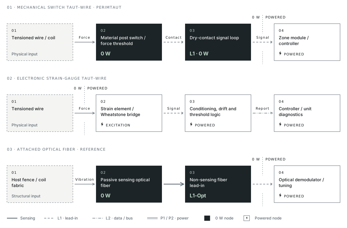
[Tensioned Wire/Coil] → [0 W Material-Based Post Switch + On-Site Adjustable Pull Threshold] → [Dry-Contact Loop] → [⚡ Powered Zone Module / Controller].
[Tensioned Wire] → [Strain Element + ⚡ Powered Bridge Excitation / Conditioning] → [Drift Algorithm + Threshold Logic] → [⚡ Line/Central Controller + Unit Diagnostics (Remote Optional Per Vendor)].
[Host Fence / Coil Fabric] → [0 W Passive Optical Fiber] → [Non-Sensing Lead-In] → [⚡ Powered Optical Demodulator + Software Tuning].
06 — Same-task comparison and specification worksheet
Evaluate Candidates on One Shared Task and Copy Verification Clauses
First compare candidate architectures against the exact same perimeter section and structural scope (Part A). Then copy or print the specification worksheet (Part B) to align tender clauses with verifiable submittals and site tests—without relying on green-check scorecards.
| Decision Dimension | PerimTaut Mechanical Switch Taut-Wire | Electronic Strain-Gauge Taut-Wire (Verify Per Model) | Attached Optical Fiber or Vibration Cable (Verify Per Model) | Condition That Shifts Selection |
|---|---|---|---|---|
| 01 · Barrier and task | Combines physical climb/spread delay with pull and wire-cut detection (TW-100 parallel wires; TW-150 verified razor-coil configuration) | Confirm whether tender scope includes full anchor posts, stays, and tensioned wires alongside sensors | Uses an existing or separately built fence/coil to carry mechanical vibration; compare complete system supply and installation scope | Existing mesh must be retained without new tension footings, or visible wire barriers are prohibited |
| 02 · Sensing chain and node power | 0 W mechanical post switches unaffected by EMI/RFI; powered backend zone modules and controllers per configuration (24-power-guide.html) | Check where excitation, bridge conditioning, multiplexing, and surge protection sit (at every sensor post, group collector, or cabinet) | Optical fiber is 0 W and EMI/RFI-unaffected (FO-750, FO-700) with powered indoor processor; check cable power per configuration on VC-600 | Long distances from perimeter to nearest power/telecom room or hazardous-area classification boundaries |
| 03 · Threshold and drift handling | All PerimTaut models feature an on-site adjustable pull threshold to filter out animal and plant contact, plus material-based slow thermal/settlement compensation | Check software/local sensitivity granularity, bridge temperature compensation, and required calibration tools | Check processor frequency/event filtering, software zone tuning, and sensitivity to wind-rattled loose mesh | Project mandates continuous per-wire tension telemetry or remote software re-profiling from a central desk |
| 04 · Alarm granularity and diagnostics | Zone intrusion and tamper contact reporting (plus anti-cut loop option on TW-150); backend interface matched per configuration | Confirm individual sensor readout, remaining-sensor survival after a cut, and whether remote control is standard or optional | Zone reporting (FO-750 4 × 300 m) or continuous meter locating (FO-700 ±4 m up to 80 km; VC-600 3 m up to 600 m) | Multi-kilometer fence patrols require pinpointed meter coordinates to steer long-range PTZ cameras |
| 05 · Civil and structural work | Concrete anchor/corner footings or verified rigid wall coping, gate terminations, and clean axial force transfer | Requires equivalent static multi-wire anchor footings and structural tension design | Minimal added static pull load, but requires repairing slack fabric, loose ties, and slapping gates before mounting | Civil foundation cost or heritage wall drilling bans outweigh new-barrier benefits |
| 06 · Commissioning and acceptance | Wire tensioning, setting the on-site adjustable pull threshold, and joint verification of animal-and-plant contact filtering plus pull/cut walk-tests | Wire tensioning, electronic/software baseline calibration, configuration backup, and pull/cut walk-tests | Splice/termination loss check, software tap/climb calibration, and coordinate-to-landmark walk-tests | Confirm gate escort windows and post foundations early so fast hardware dispatch flows straight into installation and SAT |
| 07 · Maintenance profile | Material-based core sensing structure rarely suffers damage while protective materials remain intact; routine checks focus on wires, anchors, clear zones, and powered backend | Check vendor maintenance manual for transducer/board replacement procedures, calibration drift checks, and local spares | Check splice enclosures, cable ties, host fence re-tensioning, vegetation clearing, and optical processor upkeep | Local technician skill set, spare-part holding strategy, and remote site permit rules |
| 08 · Same-scope commercial basis | Competitive pricing against equivalent high-security taut-wire systems and fast factory dispatch (confirmed per configuration) | Compare complete equal-scope BOM (posts, wires, sensors, field units, controllers, licenses, freight) and lead-time start point | Include host fence refurbishment/construction, splice labor, and processor licensing when comparing against full barriers | Civil works, import duties, or local installation scope dominate total installed project budget |
| Clause ID and Topic | Discussion Specification Wording (Editable Template) | Required Submittal and Field Verification Evidence | Responsible Role | Project Status / Notes |
|---|---|---|---|---|
| SP-01 · Target Intrusion Events | State the exact intrusion actions (wire pull, wire spreading, single-wire cut, or concertina coil cut) and barrier sections the proposed system must detect. | Zone schedule, barrier configuration drawings (TW-100 vs TW-150), and agreed pull/cut walk-test matrix. | Consultant / Owner Security | [Fill per site / Unknown] |
| SP-02 · Unpowered vs Powered Scope | Identify all perimeter components operating at 0 W without field power, and separately list every powered interface module, controller, processor, and power location. | Node-by-node topology diagram, cable schedule, and electrical load sheet for the offered configuration. | System Integrator / Electrical Eng | [Fill per site / Unknown] |
| SP-03 · On-Site Adjustable Pull Threshold | Describe how the on-site adjustable pull threshold is set to filter out animal and plant contact and how pull and cut detection are re-verified after adjustment. | Manufacturer commissioning procedure, pre/post-adjustment setting log, and witnessed pull/cut re-test record. | Manufacturer / Commissioning SI | [Fill per site / Unknown] |
| SP-04 · Nuisance Filtering vs Detection | Define both the simulated intrusion tests and the normal site conditions (wind, vegetation, adjacent traffic, HV switching) observed during commissioning. | Separate commissioning event log distinguishing intrusion tests, environmental non-intrusion triggers, and system faults. | SI / Facility Operations | [Fill per site / Unknown] |
| SP-05 · Alarm and Fault Reporting | Specify alarm granularity (zone ID or meter location), tamper/fault outputs (power loss, open/short circuit), and the verified interface to the site head-end. | Interface mapping table, point-to-point head-end demonstration, and simulated fault-injection test log. | System Integrator | [Fill per site / Unknown] |
| SP-06 · Layered Upkeep and Handover | Separate routine inspection requirements for (a) the core sensing structure, (b) external wires, coils, posts, and vegetation, and (c) powered backend hardware. | Three-layer maintenance schedule, as-built zone drawings, baseline settings record, and spare-parts list. | Owner Facilities / SI | [Fill per site / Unknown] |
07 — Barrier formats and same-scope supply
Select TW-100 or TW-150 and Compare Equal Supply Scope
Before comparing quotes or schedules across vendors, line up identical hardware and site work columns—and distinguish factory dispatch readiness from shipping, civil footings, and site commissioning.
Card 1
PerimTaut TW-100 Passive Taut-Wire Fence System
Parallel tensioned wires (9–20 cm spacing, 1–2 wires per 0 W post detector), on-site adjustable pull threshold to filter out animal and plant contact, wire-cut alarm, and self-adjusting slow-drift compensation—for freestanding fences, wall tops, and sterile inner lines.
Card 2
PerimTaut TW-150 Tension-Sensing Razor Wire Coil
Concertina razor coil with 1 internal tensioned sensing wire per 0 W detector, on-site adjustable pull threshold to filter out animal and plant contact, wire/coil-cut detection, and verified rigid wall/fence-top force transfer.
| Scope Column | Typical PerimSense Equipment Supply Scope | Project / Local Partner Scope (Confirm Per Order) | Delivery Stage Note |
|---|---|---|---|
| Barrier and post hardware | Detector posts, specified tensioning hardware, wires or monitored coils per agreed BOM | Concrete footings, wall coping reinforcement, gates, and local civil erection labor | Stage 1 · Factory Dispatch: Fast PerimTaut factory dispatch confirmed against agreed configuration and order quantity |
| Sensing and backend electronics | 0 W mechanical post detectors + selected 24 VDC zone modules / 9–24 VDC controllers (per configuration) | Field signal/power conduits, indoor racks, UPS backup, surge earthing, and VMS/panel integration | Stages 2–4 · Freight, Civil, and SAT: Ocean/air transit, customs clearance, civil curing, and site acceptance depend on project location and contractors |
- Prompt: Bring your approximate boundary length, preferred barrier format (TW-100 or TW-150), and specification worksheet notes for a preliminary zone proposal and equal-scope equipment supply quote.
- Next Guide Links: Next step in planning: Passive Sensing, System Power, and Wiring Architecture · Installation, Commissioning, and Maintenance Checklist →