Home/Products/PerimForce PM-280
PerimForce PM-280 · Covert Pressure-Sensing Detection System

Turn Critical Floor Thresholds into Invisible Alarm Triggers.

Catch intruders the instant they step onto a restricted threshold or walkway without exposing a single visible detector. PerimForce PM-280 pairs edge-to-center mechanical force compensation with ≥36 mm pads, 9/12 mm 0 W mats, and 44 mm 1-to-4 modules for ≤1 s alarms.
Share your threshold dimensions and floor finish for a preliminary surface layout and equipment supply quote.
Defined Pressure-Sensing Surface010203
01Pressure mat · 9 mm / 12 mm · 0 W · 204.8 kg
02Integrated pad · ≥36 mm · 100 kg
031-to-4 module · 44 mm · 400 kg
Defined pressure-sensing surface
Full-Surface Footstep Catch
≤1 s
Edge-to-center force compensation eliminates dead-edge missed steps
Ultra-Thin Interior Concealment
9 mm / 12 mm
0 W passive pressure mats handling up to 204.8 kg per unit
Two-Stage Threshold Control
>30 kg
Default alarm load with adjustable warning and alarm levels
Minimal Field Power Draw
≤2 W
12–24 VDC powered pads and 400 kg 1-to-4 modules on IP66 housings
01 — Key capabilities

Twelve Reasons Security Teams Specify PM-280 Underfoot

01

Conceal Sensing Inside the Surface

01

3 Purpose-Built Formats

Match floor depth with ≥36 mm pads, 9/12 mm mats, or 44 mm modules.

02

Custom Surface Finish

Tailor dimensions and top finishes to blend invisibly into surrounding floors.

03

9 mm Ultra-Thin Mats

Slip 9 mm or 12 mm 0 W mats under indoor floor coverings.

04

Point or Corridor Cascading

Link units across isolated doorways or cascade continuous monitored walkways.

02

Catch Edge Steps Without False Alarms

05

Edge-to-Center Force Balance

Equalize edge and center footstep loads mechanically before sensor digitization.

06

Dual Adjustable Thresholds

Set independent warning and >30 kg alarm levels on pads and modules.

07

Adaptive Weighing Logic

Evaluate force, contact duration, and ambient drift before triggering any alarm.

08

≤1 s Rapid Actuation

Deliver verified footstep alarms to security operators within ≤1 s.

03

Simplify Power, Weather, and Integration

09

≤2 W Unit Power

Run powered units on 12–24 VDC at ≤2 W while mats sense at 0 W.

10

-40°C to +70°C Outdoor Pads

Deploy IP66 pads and 400 kg 1-to-4 modules across -40°C to +70°C thresholds.

11

Integrated Tamper Alarms

Trigger immediate security alerts whenever an intruder pries or lifts the housing.

12

Ethernet and POWER BUS

Report events over Ethernet, POWER BUS, or Modbus RTU controller links.

02 — Operating principle

How a Footstep on the Surface Becomes a Verified Alarm in ≤1 s

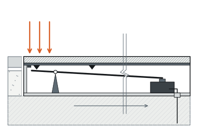
When an intruder steps onto an armed PM-280 detection surface, downward load passes through the custom top plate into a purpose-built mechanical force-transfer structure.
Edge-to-Center Load Transfer
01
Edge-to-center load transfer
Mechanical compensation + pressure sensor
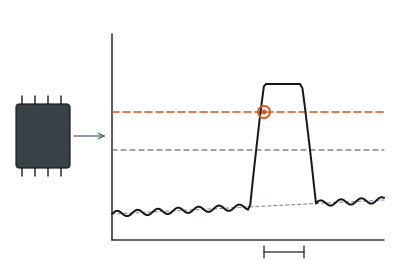
Adaptive Weighing Evaluation
02
Adaptive weighing evaluation
Force + duration + environment vs >30 kg threshold
Controller Event Dispatch
03
Controller event dispatch
≤1 s output · Ethernet / POWER BUS / Modbus RTU

This mechanism equalizes force differences between edge steps and center steps before transferring load to the internal pressure sensor for analog-to-digital conversion.

Onboard microprocessor weighing algorithms evaluate force magnitude, contact duration, and ambient temperature drift against preset warning and alarm thresholds (>30 kg default, independently adjustable on ≥36 mm pads and 44 mm 1-to-4 modules; 9/12 mm mats use a 0 W passive sensing element with powered backend evaluation).

Confirmed alarms reach the controller in ≤1 s via Ethernet or POWER BUS.

03 — Full-footprint reliability

Step on the Dead Edge or Shift the Weather—Detection Stays Uniform.

Conventional floor pressure switches fail in two predictable ways: intruders hugging a wall step onto a stiff corner edge without tripping the center load cell, while seasonal temperature swings warp floor finishes until static expansion triggers phantom midnight alarms.

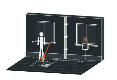
PM-280 eliminates dead edges inside its mechanical force-transfer chassis, routing off-center corner loads cleanly into the sensor before analog-to-digital sampling begins.
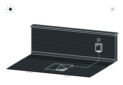
Slow Ambient Drift (-40°C to +70°C)
State A
Slow ambient drift (-40°C to +70°C)
Adaptive baseline tracking · No false alarm
Off-Center Edge Footstep
State B
Off-center edge footstep
Mechanical force compensation · Alarm ≤1 s
Direct Center Footstep
State C
Direct center footstep
Exceeds >30 kg adjustable threshold · Alarm ≤1 s

Next, microprocessor weighing logic evaluates load magnitude alongside dwell duration and gradual ambient drift, automatically adapting baseline parameters across -40°C to +70°C on pads and modules (-10°C to +55°C on mats) while firing real footstep alarms in ≤1 s.

04 — Field deployment

Engineered for the boundary you operate.

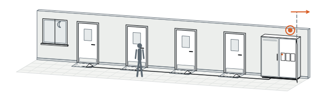
Scenario 01 · Secure-Room Vestibules

Monitor Restricted Thresholds Without Revealing Where Detection Starts

Visible wall beams and ceiling sensors inside a vault vestibule telegraph the exact line an intruder tries to step over or mask. PM-280 embeds a flush, imperceptible ≥36 mm pressure pad (100 kg max unit load) directly across the doorway approach so the floor looks untouched. Edge-to-center compensation and independent warning and >30 kg alarm thresholds catch anyone crossing the threshold in ≤1 s.

Plan this perimeter →
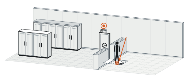
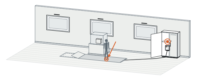
Secure-room vestibule layout
Outer Corridor
Outer corridor
Flush PM-280 pad
≥36 mm · 100 kg
Edge-to-center uniform catch
Secure vault / server room
≤1 s cue
04 — Field deployment

Engineered for the boundary you operate.

Scenario 02 · Museums and Heritage Interiors

Protect Curated Galleries with 9 mm Passive Mats—Without Cutting Historic Floors

Chiseling deep floor trenches or bolting detector brackets onto heritage stonework ruins curated sightlines and stalls interior security upgrades. PM-280 offers 9 mm ultra-thin and 12 mm standard pressure mats whose sensing elements operate at 0 W across -10°C to +55°C while supporting up to 204.8 kg per unit. Security planners define exact stand-off perimeters under runners or display approaches while keeping powered evaluation hardware tucked out of sight.

Plan this perimeter →
Low-profile gallery deployment
Protected Exhibit Stand-Off Perimeter
Protected exhibit stand-off perimeter
Floor runner lift-away view
0 W pressure mat
9 mm / 12 mm · 204.8 kg
Concealed backend processing
-10°C to +55°C
04 — Field deployment

Engineered for the boundary you operate.

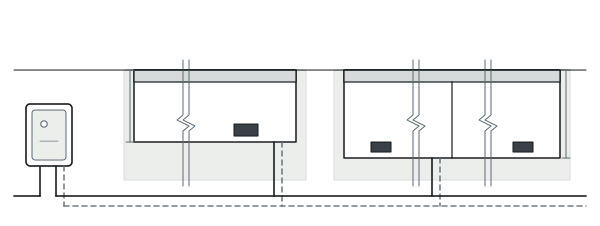
Scenario 03 · Data-Center Service Corridors

Cover Fragmented Raised-Floor Access Points with 400 kg 1-to-4 Modules

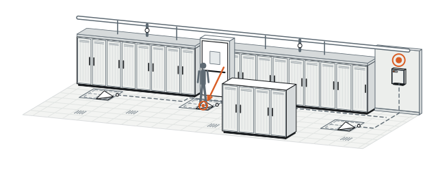
Cooling manifolds, busway drops, and fire doors break data-center service corridors into short zig-zag segments where line-of-sight beams leave blind pockets. PM-280’s 44 mm 1-to-4 pressure module handles up to 400 kg per unit and deploys across separated access nodes or cascaded walkway strips. Each monitored node maintains independent warning and >30 kg alarm thresholds while drawing ≤2 W at 12–24 VDC.

Plan this perimeter →
Data-center corridor plan
Segmented Service Corridor
Segmented service corridor
1-to-4 pressure module
44 mm · 400 kg
Dispersed doorway node
>30 kg threshold
12–24 VDC
≤2 W → zone controller
04 — Field deployment

Engineered for the boundary you operate.

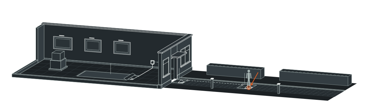
Scenario 04 · Landscaped Estate Approaches

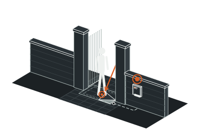
Keep Courtyard Walkways Visually Clean Across -40°C to +70°C Weather

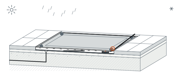
Estate owners reject industrial fence hardware and camera poles beside garden approaches, yet exposed courtyard paths endure rain, snow, dust, and wide temperature swings. PM-280 seals its powered pad (≥36 mm) and module (44 mm) assemblies to IP66 for dependable outdoor service from -40°C to +70°C. Custom top finishes match surrounding walkway sections while built-in tamper protection guards the buried housing against prying.

Plan this perimeter →
Outdoor courtyard walkway section
Custom-Matched Walkway Surface
Custom-matched walkway surface
IP66 sealed detector housing
-40°C to +70°C
Pad (≥36 mm) / module (44 mm) base
Built-in housing tamper switch
04 — Field deployment

Engineered for the boundary you operate.

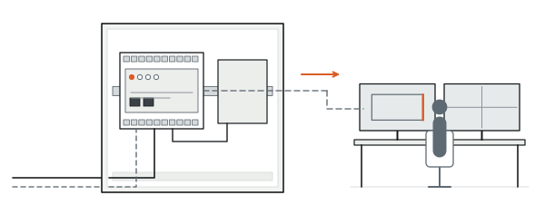
Scenario 05 · After-Hours Campus Routes

Cascade Multi-Point Floor Zones Onto One Clean Controller Bus

Office and research buildings have shared corridors that stay open all day but turn into high-risk bypass routes overnight, where home-running cables from dozens of doors inflates installation cost. PM-280 cascades multiple ≤2 W sensing units along Ethernet or POWER BUS into a nearby controller (with dry-contact trigger and Modbus RTU controller support) for scheduled night arming via the upper security platform. Adaptive force-and-time processing filters static floor stress so overnight operators only receive actionable intrusion events.

Plan this perimeter →
Multi-threshold corridor cascading
Daytime Open / Night-Armed Corridor Nodes
Daytime open / night-armed corridor nodes
Cascaded PM-280 units
≤2 W each
POWER BUS / Ethernet / dry contact
Local controller (Modbus RTU) → security platform
05 — System architecture and bill of subsystems

How 0 W Passive Mats, Powered Pads/Modules, and Controllers Fit Together

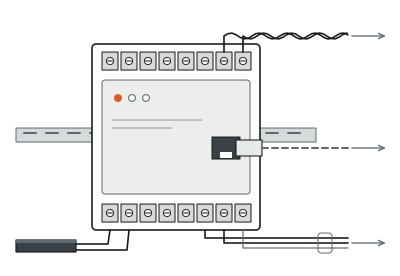
PM-280 clearly distinguishes its 0 W passive pressure-mat sensing element from its 12–24 VDC powered pads, 1-to-4 modules, and upstream controllers—keeping floor recess prep, low-voltage bus wiring, and platform integration unambiguous.
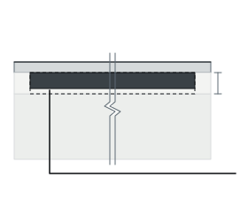
FIELD ASSEMBLY0 WIndoor or sheltered threshold floor layer
0 W Passive Mat + Evaluation Unit9 / 12 mm
Branch A
0 W passive mat + evaluation unit
9/12 mm · 204.8 kg
FIELD ASSEMBLYPoweredRecessed indoor/outdoor access point or cascaded route
Cascaded IP66 Pads≥36 mm44 mm
Branch B
Cascaded IP66 pads
≥36 mm · 100 kg · 12–24 VDC, ≤2 W
Branch C
1-to-4 module
44 mm · 400 kg · 12–24 VDC, ≤2 W
PROCESSING / CONTROLPoweredNearby low-voltage closet or control room
Ethernet / POWER BUS / Dry-Contact Bus
04
Ethernet / POWER BUS / dry-contact bus
≤1 s
05
Nearest PM-280 controller
Modbus RTU / Ethernet
06
Upper security management platform

System components and trade interfaces

Subsystem Layer
Components Included
Power Status
Location and Trade Scope
01 · Passive Pressure-Mat Sensing Element
Ultra-thin (9 mm) or standard (12 mm) custom pressure-sensing mat rated up to 204.8 kg max load per unit (-10°C to +55°C)
0 W (Unpowered sensing mat)
Indoor or sheltered threshold floor layer · Interior finish installation
02 · Powered Pressure Pads and 1-to-4 Modules
≥36 mm integrated pad (100 kg max) or 44 mm 1-to-4 module (400 kg max) with mechanical compensation, pressure sensor, microprocessor, and IP66 housing (-40°C to +70°C)
Powered (12–24 VDC, ≤2 W per unit)
Recessed indoor/outdoor access point or cascaded route · Civil recess and LV wiring
03 · Field Bus and Tamper Supervision
Ethernet, POWER BUS, or dry-contact/bus interconnect cabling carrying pre-warning, >30 kg alarm, and housing tamper events
Powered via 12–24 VDC bus / signal loop
Concealed floor conduit or riser · Security integrator cabling
04 · Local Controller and Site Platform Link
Nearest PM-280 controller aggregating cascaded units and interfacing via Ethernet or Modbus RTU to the site VMS/PSIM
Powered (Equipment room / local cabinet supply)
Nearby low-voltage closet or control room · SI commissioning
06 — Technical specifications

PerimForce PM-280 Full Engineering Specifications

Physical Formats
Parameter
Standard Specification
Integrated Pressure Pad
Thickness ≥36 mm; maximum load 100 kg per unit; powered (12–24 VDC, ≤2 W); -40°C to +70°C
Pressure Mat (Ultra-Thin / Standard)
Thickness 9 mm (ultra-thin) / 12 mm (standard); maximum load 204.8 kg per unit; 0 W passive sensing element; -10°C to +55°C
1-to-4 Pressure Module
Thickness 44 mm; maximum load 400 kg per unit; powered (12–24 VDC, ≤2 W); -40°C to +70°C
Surface Customization and Layout
Custom detection dimensions and surface finish; supports dispersed multi-point or continuous cascaded deployment
Detection Performance
Parameter
Standard Specification
Sensing and Force Compensation
Dedicated mechanical force-transfer structure equalizes edge and center loading prior to A/D conversion
Signal Evaluation Algorithm
Microprocessor weighing algorithm evaluates force magnitude, duration, and environmental changes with self-adaptation
Default and Adjustable Thresholds
Default alarm trigger >30 kg; independently adjustable warning and alarm thresholds on pad and module layouts
Alarm Response Time
≤1 s
Underfoot Trigger Characteristic
Imperceptible underfoot deflection (excluding standard 12 mm pressure mat)
Electrical and Interfaces
Parameter
Standard Specification
Powered-Unit Input Voltage
12–24 VDC (pressure-mat sensing element operates at 0 W)
Standalone Unit Power Consumption
≤2 W per powered unit (excludes upstream controller budget)
Unit-to-Controller Reporting
Ethernet or POWER BUS; dry-contact trigger or bus communication
Controller Communication Interface
Modbus RTU and upstream security platform networking
Protection and Environment
Parameter
Standard Specification
Tamper Supervision
Built-in assembly tamper protection
Detector Enclosure Rating
IP66 dustproof and waterproof protection
Environmental Resilience
Unaffected by wind, rain, hail, snow, dust, UV exposure, temperature swings, and EMI on outdoor pad/module layouts

Above values reflect standard product technical specifications. Custom surface dimensions, finish material stack-up, and cascade bus lengths are matched to your project drawings during design.

07 — Engineering FAQ

Common Questions Before Specifying PM-280

01How do we choose between the ≥36 mm pad, 9/12 mm mat, and 44 mm 1-to-4 module?

Select the 9 mm ultra-thin or 12 mm standard 0 W mat (204.8 kg max load, -10°C to +55°C) for indoor floors where recess depth is minimal. Choose the ≥36 mm integrated pad (100 kg) or 44 mm 1-to-4 module (400 kg) when you need IP66 outdoor durability (-40°C to +70°C) and independently adjustable warning and >30 kg alarm thresholds.

02When should a project specify PM-280 pressure surfaces instead of BF-300 buried RF cables?

Specify PM-280 when you want footsteps on a strictly bounded doorway, walkway, or indoor gallery strip to trigger an alarm in ≤1 s without sensing movement outside that exact surface. Specify PerimTerra BF-300 when you need a continuous underground outdoor perimeter up to 800 m per processor (1 m high, 2–3 m wide volumetric field) with ±1 m intrusion locating and waterway crossings.

03Can heavy equipment carts or vehicles drive across PM-280 units?

PM-280 maximum load ratings per unit are 100 kg (pad), 204.8 kg (mat), and 400 kg (1-to-4 module) for pedestrian thresholds and equipment corridors. For wide vehicle roadways or open gate spans, pair the vehicle lane with a fixed bistatic microwave link such as PerimWave MW-400 (5–200 m) while keeping PM-280 on pedestrian approaches.

04What floor preparation and cabling are needed to integrate PM-280 into our VMS?

Powered pads and modules require a level recessed pocket matching ≥36 mm or 44 mm thickness plus a 12–24 VDC (≤2 W per unit) POWER BUS or Ethernet conduit back to the local controller, whereas 9/12 mm mats lay beneath indoor coverings. Upstream controllers expose Ethernet and Modbus RTU/dry-contact links for straightforward VMS and PSIM integration.

08 — Next step

Get a Preliminary PM-280 Surface Layout and Equipment Supply Quote

Send us your floor plan, doorway widths, or walkway dimensions. Our engineering team will recommend the right pad, mat, or 1-to-4 module format, map cascade bus routing to the controller, and prepare an equipment supply quotation.

01Dimensions and count of doorways, thresholds, or corridor strips to monitor
02Indoor or outdoor environment, recess depth available (9/12 mm, ≥36 mm, or 44 mm), and surface finish
03Expected maximum static/foot load on each surface (up to 100 kg, 204.8 kg, or 400 kg)
04Controller location and preferred reporting link (Ethernet, POWER BUS, Modbus RTU, or dry contacts)
Data Centers ↗Private Estates ↗Commercial and Logistics ↗Substations ↗How PIDS Works ↗Power Planning Guide ↗Installation and Maintenance ↗Compare All Products ↗