Home/Products/PerimOptic FO-700
PerimOptic FO-700 · Long-Range Locating Fiber-Optic Intrusion Detection

Pinpoint Intrusions Across Tens of Kilometers. Keep Detecting After a Cut.

Pinpoint climbs, cuts, and digging within typical ±4 m across tens of kilometers—with 0 W of electronics outdoors. PerimOptic FO-700 monitors up to 80 km of fence or 100 km of buried fiber from a single indoor processor, keeping active detection right up to a fiber break.
Send your route map or perimeter mileage for a preliminary zone proposal and equipment supply quote.
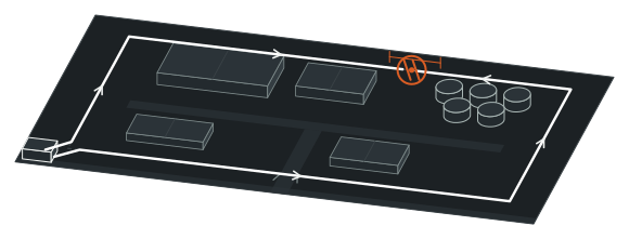
Up to 1,440 software-defined zones010203Event A · 14,320 m±4 mEvent B · 41,850 m±4 m
01Control room · FO-700 interrogation unit
02Fence-mounted sensing route · Up to 80 km
03Buried sensing route · Up to 100 km
Up to 1,440 software-defined zones
One-Rack Corridor Reach
80 / 100 km
Up to 80 km fence-mounted or 100 km buried sensing fiber
Pinpoint Camera Slew
±4 m
Typical intrusion location accuracy for instant PTZ targeting
Granular Software Sectors
1,440
Configurable alarm zones resized anytime without field rewiring
Cut-Proof Ring Continuity
±30 m
Pinpoints cable cuts while sensing continues up to the break
01 — Key capabilities

Twelve Reasons Large Perimeters Standardize on FO-700

01

Pinpoint Threats Across Long Routes

01

80 km Fence / 100 km Buried

Cover sprawling industrial perimeters or pipeline corridors from one indoor rack.

02

Typical ±4 m Location

Slew PTZ cameras and guide patrol vehicles straight to the breach.

03

15 m / 30 m Multi-Event Split

Resolve simultaneous intrusions 15 m apart (linear) or 30 m apart (ring).

04

1,440 Software Zones

Carve continuous fiber into granular gate, tank, and patrol sectors.

02

Stay Armed Through Cuts and Weather

05

Redundant Ring Cut Immunity

Stop a single deliberate cut or trenching strike from blinding downstream miles.

06

Sensing Right Up to Break

Interrogate from both ring ends so every connected meter stays armed.

07

±30 m Cut Pinpointing

Send splice crews straight to the sever within ±30 m accuracy.

08

<1 Alarm/km/Month, >87,000 h MTBF

Reject wind and rain noise with <1 alarm/km/month and >87,000 h MTBF.

03

Strip Out Field Infrastructure

09

0 W Passive Outdoor Zone

Eliminate field power trenching, outdoor switches, and sensor ground rods.

10

EMI and Lightning Immune

Route dielectric glass fiber safely beside HV switchyards and tank farms.

11

Fence + Buried Mixed Routing

Transition from mesh fencing to underground crossings on one continuous cable.

12

Standard 1,550 nm Telecom Fiber

Use standard single-mode cable (0.25 dB/km, ≥4 to 24 cores, -40°C to +70°C).

02 — Operating principle

How 1,550 nm Laser Reflections Pinpoint a Breach Along 100 km of Fiber
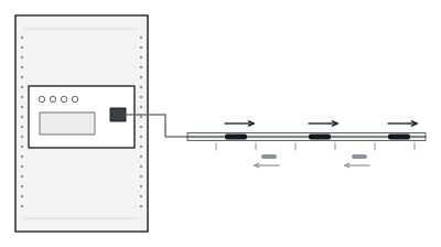
Laser pulse interrogation
01
Laser pulse interrogation
1,550 nm
Single-mode fiber · 0.25 dB/km

From a safe indoor rack, the FO-700 processor launches coherent 1,550 nm laser pulses into a single-mode optical fiber and measures minute backscatter reflections returning from every meter of route.
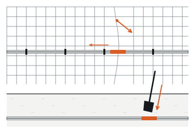
Localized reflection shift
02
Localized reflection shift
Fence climb / cut or ground digging

Climbing, cutting, or prying a fence—or footsteps and excavation vibrating soil above buried cable—alters the phase and intensity of light reflected at that exact spot.
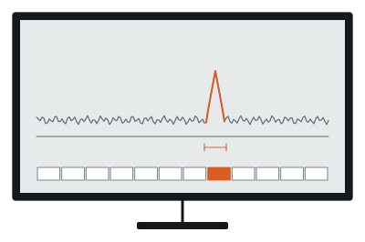
Located intrusion alarm±4 m
03
Located intrusion alarm
Signature filtering · up to 1,440 zones

High-speed signal processing filters out uniform wind and rain noise, calculates time-of-flight distance within typical ±4 m, and assigns the event to its matching software zone.

03 — Cut-resilient architecture

A Cable Cut Never Blinds the Route: Active Sensing Up to the Break and ±30 m Cut ID.

On an 80 km fence or 100 km pipeline corridor, the worst security failure is a single wire snip or accidental backhoe strike silencing miles of downstream perimeter.
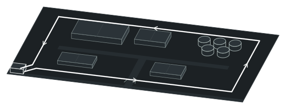
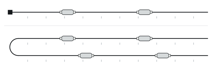
Normal Redundant Ring
State A
Normal redundant ring
Closed optical loop · Full perimeter armed (±4 m)

FO-700 eliminates that single point of failure with a closed redundant ring topology.
Active Protection After Cable Cut±30 mPath A activePath B active
State B
Active protection after cable cut
Path A active up to cut
Path B active up to cut
Cable cut pinpointed within ±30 m

If the cable is severed anywhere, the processor immediately raises a cut alarm, pinpoints the break within ±30 m for rapid splicing, and interrogates from both ends of the ring—keeping every connected meter right up to the cut fully armed.

04 — Field deployment

Engineered for the boundary you operate.

Scenario 01 · Pinpoint Camera and Patrol Dispatch

Slew PTZ Cameras Within ±4 m—Even During Coordinated Multi-Point Attacks

A coarse zone alarm on a dark multi-kilometer airfield or refinery fence leaves guards panning cameras blindly while intruders slip inside. FO-700 narrows every breach to a typical ±4 m coordinate so PTZ cameras lock onto the target and patrols head straight to the nearest gate. Decoy distractions fail too: simultaneous events ≥15 m apart in linear mode—or ≥30 m apart in redundant ring mode—report independently.

Plan this perimeter →
LOCATION ACCURACY ≠ EVENT SEPARATION
Event 01±4 m±4 m15 m linear / 30 m redundant
Event 01
±4 m window
Event 02
±4 m window
Minimum multi-event separation
15 m linear / 30 m redundant
PTZ preset slew
04 — Field deployment

Engineered for the boundary you operate.

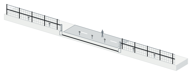
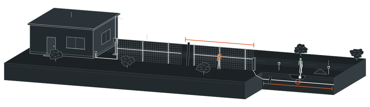
Scenario 02 · Mixed Fence and Underground Routing

Bridge Fence Runs, Open Buffer Strips, and Road Aprons Without Sensor Gaps

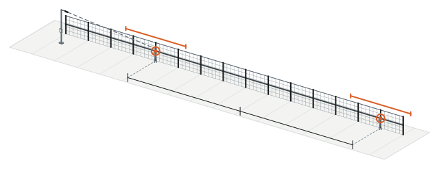
Switching sensor technologies every time a fence meets a road crossing, open buffer strip, or un-fenced approach creates blind handoff seams and spare-parts sprawl. FO-700 runs one continuous optical cable along mesh fencing, dives underground beneath open corridors and gate aprons, and climbs right back onto the next fence span—maintaining calibrated meter-by-meter locating across the entire mixed route.

Plan this perimeter →
ONE FIBER. ABOVE AND BELOW GRADE.
Section AA · Fence-mountedB · BuriedC · Fence-mounted
Section A
Fence-mounted fiber
Transition conduit
Section B
Buried concealed fiber
Section C
Fence-mounted fiber
Total optical cable length tracked by meter marker
04 — Field deployment

Engineered for the boundary you operate.

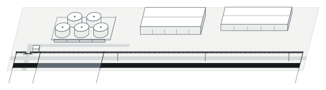
Scenario 03 · Granular Operational Zoning

Resize Up to 1,440 Security Sectors in Software—Without Touching Field Cable

Hardwired field zones freeze your security map to wherever junction boxes were bolted during phase-one construction. FO-700 divides one physical fiber into up to 1,440 software-defined detection zones. Assign tight 30 m sectors around tank manifolds and gates, group 250 m runs along straight patrol roads, and redraw sector boundaries in minutes whenever cameras or site phases expand.

Plan this perimeter →
ONE PHYSICAL FIBER / SOFTWARE ZONES
Continuous Passive Optical CableZ-01Z-02Z-0330 m80 m250 m
Continuous passive optical cable
Zone Z-01
30 m · Gate flank
Zone Z-02
80 m · Tank manifold
Zone Z-03
250 m · Patrol fence
Up to 1,440 configurable zones
04 — Field deployment

Engineered for the boundary you operate.

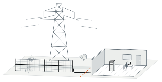
Scenario 04 · Zero-Power Hazardous and High-EMI Corridors

Cut Civil Trenching Budgets across LNG Terminals, Solar Farms, and Rail Lines

Trenching copper power, surge arrestors, and active field cabinets across tens of kilometers of desert solar fencing or petrochemical corridors often costs more than the detection system itself. FO-700 keeps 100% of powered electronics inside one safe-area rack. Outdoors, the 0 W dielectric optical cable needs zero power, zero field switches, and zero sensor ground rods—immune to lightning strikes and HV transients.

Plan this perimeter →
OUTDOOR PASSIVE / INDOOR POWERED
Outdoor Perimeter / Hazardous Corridor0 WSafe-area room
Outdoor perimeter / hazardous corridor
0 W dielectric optical fiber
Immune to EMI and lightning
Zero field power
Zero sensor grounding
Safe-area rack
FO-700 processor
04 — Field deployment

Engineered for the boundary you operate.

Scenario 05 · Pipeline Right-of-Way and Harsh-Climate Durability

Catch Backhoes and Illegal Tapping Along 100 km of Buried Right-of-Way

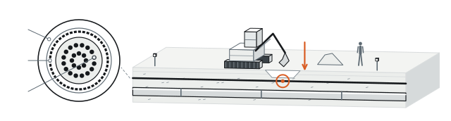
Unreported third-party excavation and heavy machinery strikes cause catastrophic pipeline ruptures and backbone outages before patrol cars ever pass by. Buried above oil, gas, or telecom conduits, FO-700 monitors up to 100 km per unit to catch mechanical digging early. Standard 1,550 nm single-mode telecom cable (0.25 dB/km, ≥4 to recommended 24 cores, UV-resistant loose tube, optional single armor) endures -40°C to +70°C.

Plan this perimeter →
TELECOM-GRADE FIBER / PIPELINE PROTECTION
UV-Resistant Outer Jacket01020304
01
UV-resistant outer jacket
02
Optional single armor layer
03
Loose tube + 4 to 24 single-mode fibers
1,550 nm
04
Buried pipeline corridor · Up to 100 km
±4 m location
05 — System architecture and bill of subsystems

Zero Active Hardware Outdoors—Everything Powered Stays in One Rack

FO-700 reduces tens of kilometers of perimeter construction to standard single-mode fiber outdoors and a single interrogation processor indoors.
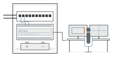
LINEAR OR REDUNDANT / CENTRALIZED PROCESSING
Outdoor perimeter / hazardous corridor0 W (Unpowered)Fence-mounted (up to 80 km), buried (up to 100 km), or mixed route
Topology A · Linear Configuration
01
Topology A · Linear configuration
15 m multi-event resolution
02
Topology B · Redundant ring configuration
30 m multi-event resolution · Cut-resilient
03
Passive optical splice closure
0 W
Indoor powered processorPoweredSafe-area control room or telecom room
Indoor ODF + FO-700 Processor
04
Indoor ODF + FO-700 processor
>87,000 h MTBF
05
Multi-platform VMS / PSIM / camera integration

System components and trade interfaces

Subsystem Layer
Components Included
Power Status
Location and Trade Scope
01 · Passive Sensing Optical Cable
1,550 nm single-mode telecom optical cable (24-core recommended, ≥4 cores minimum; UV-resistant loose tube; optional single armor for buried/rodent-exposed runs)
0 W (Unpowered)
Fence-mounted (up to 80 km), buried (up to 100 km), or mixed route · Fence / civil / fiber crew
02 · Passive Route Splice Hardware
Weatherproof optical splice closures, fence UV cable ties or conduit clips, and route meter calibration markers
0 W (Unpowered)
Outdoor perimeter or buried handholes · Fiber installation crew
03 · Optical Patch and Return Loop
Rack optical distribution frame (ODF) termination; single-ended linear termination or closed redundant ring return fiber
0 W (Unpowered)
Indoor telecom / security equipment room · Fiber termination
04 · FO-700 Interrogation Processor
FO-700 optical detection and locating processor (>87,000 h MTBF; up to 1,440 software zones) interfacing with site VMS, PSIM, and alarm management platforms
Powered (Indoor rack / UPS-backed)
Safe-area control room or telecom room · SI commissioning
06 — Technical specifications

PerimOptic FO-700 Full Engineering Specifications

Locating and Coverage
Parameter
Standard Specification
Maximum Sensing Cable Length
Up to 80 km (fence-mounted installation); up to 100 km (buried installation)
Intrusion Location Accuracy
Typical ±4 m
Software-Defined Zones
Up to 1,440 configurable detection zones
Multi-Event Spatial Resolution
15 m minimum separation (non-redundant linear mode); 30 m minimum separation (redundant ring mode)
Cut Resilience and Reliability
Parameter
Standard Specification
Redundant Cut Protection
Configurable anti-cut redundant ring mode; active intrusion detection continues right up to the cable break
Cable-Cut Location Accuracy
±30 m
Typical Nuisance Alarm Rate (FAR)
<1 alarm/km/month
Processor Mean Time Between Failures
>87,000 h MTBF
Optical Sensing Cable
Parameter
Standard Specification
Fiber Type and Operating Wavelength
Telecom-grade single-mode optical fiber; 1,550 nm wavelength
Optical Attenuation
0.25 dB/km at 1,550 nm
Recommended Fiber Core Count
24-core telecom optical cable recommended (minimum ≥4 cores)
Cable Jacket and Armor Options
UV-resistant outer sheath, loose-tube construction, optional single armor
Deployment and Environment
Parameter
Standard Specification
Supported Route Topologies
Fence-mounted, buried, or alternating mixed installation; linear or redundant ring topology
Field Zone Electrical Profile and Temp
0 W passive outdoor sensing zone (immune to EMI and lightning, zero field grounding); -40°C to +70°C cable rating

Above values reflect standard product technical specifications. Optical link loss budgets, redundant ring fiber core assignments, and host integration interfaces are finalized against your route map during project design.

07 — Engineering FAQ

Common Questions Before Specifying FO-700

01When should we specify FO-700 locating fiber versus FO-750 zoned fiber?

Choose PerimOptic FO-700 for multi-kilometer perimeters, pipelines, airfields, or rail corridors needing continuous ±4 m coordinates, up to 80/100 km reach, 1,440 software zones, or cut-resilient ring protection. Choose PerimOptic FO-750 for compact perimeter stations (4 zones × up to 300 m per 2 W PoE-capable processor, with up to 20 km non-sensing lead-in fiber).

02Does the 80 km / 100 km rating refer to site perimeter or total sensing cable length?

The 80 km fence and 100 km buried ratings specify total monitored optical cable length—including slack loops, vertical drops, and return routing. During preliminary design, our engineers calculate your fiber path and splice loss budget (at 0.25 dB/km, 1,550 nm) to size linear or closed-ring topologies accurately.

03What is the practical difference between ±4 m location accuracy and 15 m / 30 m spatial resolution?

±4 m is how accurately FO-700 pinpoints an intrusion along the calibrated cable route. The 15 m (linear) and 30 m (redundant) figures define the minimum distance between two simultaneous disturbances for the processor to report them as two separate events at the same instant.

04Does FO-700 lock us into proprietary optical cable or specialized field splicing tools?

No—FO-700 runs over standard telecom-grade 1,550 nm single-mode loose-tube optical cable (24-core recommended, ≥4 cores minimum, UV-resistant sheath, optional single armor for direct burial or rodent zones), so standard fiber crews splice and repair it with conventional fusion splicers.

08 — Next step

Get a Preliminary FO-700 Route Plan and Equipment Supply Quote

Share your perimeter route or pipeline corridor mileage—fence-mounted, buried, or mixed. Our engineers will evaluate linear versus redundant ring topology, software zoning, and cable armor options, and prepare an equipment supply quotation.

01Total route mileage and split between fence-mounted and buried sections
02Host fence type or burial surface (soil, gravel, road crossings, pipeline depth)
03Preferred topology (linear single-feed or cut-resilient redundant ring) and indoor rack room
04PTZ camera layout and target VMS, PSIM, or alarm platform interface
Oil and Gas Terminals ↗Airports ↗Solar and Battery Storage ↗Data Centers ↗How It Works ↗Power Planning Guide ↗Installation and Maintenance ↗Compare All Products ↗